EN 24 YASKAWA Europe TOMP_C710606_75A V1000 IP66 - Quick Start Guide
7 Troubleshooting
7 Troubleshooting
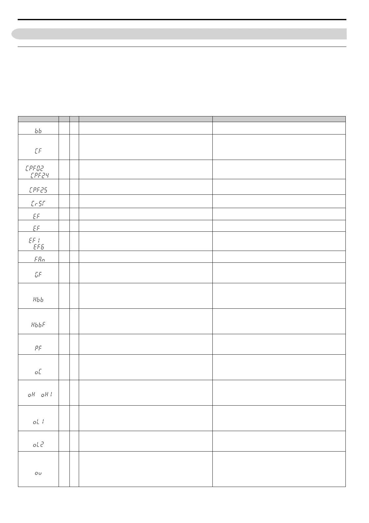
General Fault and Alarms
Faults and alarms indicate problems in the drive or in the machine.
An alarm is indicated by a code on the data display and the flashing ALM LED. The drive output is not necessarily switched off.
A fault is indicated by a code on the data display and the ALM LED is on. The drive output is always switched off immediately and the motor coast
to stop.
To remove an alarm or reset a fault, trace the cause, remove it and reset the drive by pushing the Reset key on the operator or cycling the power
supply.
This lists up the most important alarms and faults only. Please refer to the Technical Manual for a complete list.
LED Display ALM FLT Cause Corrective Action
Base Block
The software base block function is assigned to one of the digital inputs and
the input is off. The drive does not accept Run commands.
• Check the digital inputs function selection.
• Check the upper controller sequence.
Control Fault
The torque limit was reached during deceleration for longer than 3 sec.
when in Open Loop Vector control
• The load inertia is too big.
• The torque limit is too low.
• The motor parameters are wrong.
• Check the load.
• Set the torque limit to the most appropriate setting (L7-01 through L7-
04).
• Check the motor parameters.
Control Circuit Fault
There is a problem in the drive’s control circuit.
• Cycle the drive power supply.
• Initialize the drive.
• Replace the drive if the fault occurs again.
Control Circuit Fault
There is no terminal board connected to the control board or the connection
is broken.
• Check if the terminal board is installed properly.
• Uninstall and Reapply the terminal board.
• Change the drive.
Cannot Reset
Fault reset was input when a Run command was active. Turn off the Run command and reset the drive.
Option External Fault
An external fault was tripped by the upper controller via an option card.
• Remove the fault cause, reset the fault and restart the drive.
• Check the upper controller program.
External Fault
A forward and reverse command were input simultaneously for longer than
500 ms. This alarm stops a running motor.
Check the sequence and make sure that the forward and reverse input are
not set at the same time.
External Faults
• An external fault was triggered by an external device via one of the
digital inputs S1 to S6.
• The digital inputs are set up incorrectly.
• Find out why the device tripped the EF. Remove the cause and reset the
fault.
• Check the functions assigned to the digital inputs.
Internal Fan Alarm
• Internal stirring fan does not work
• Replace internal fan (see fig. Replacing the Internal Stirring Fan on
page 27)
Ground Fault
Ground leakage current has exceeded 50% of the drives rated output
current.
• Cable or motor insulation is broken.
• Excessive stray capacitance at drive output.
• Check the output wiring and the motor for short circuits or broken
insulation. Replace any broken parts.
• Reduce the carrier frequency.
Drive Disable
Both Drive Disable inputs are open. The drive output is safely disabled and
the motor can not be started.
• Check why the upper controller’s safety device disabled the drive.
Remove the cause and restart.
• Check the wiring. If the Drive Disable function is not utilized for
EN60204-1, stop cat. 0 or for disabling the drive, the terminals HC, H1,
H2 must be linked.
Drive Disable Fault
Drive output is disabled while only one of the Drive Disable inputs is open.
(normally both input signals H1 and H2 should be open)
• One channel is internally broken and does not switch off, even if the
external signal is removed.
• Only one channel is switched off by the upper controller.
• Check the wiring from the upper controller and make sure that both
signals are set correctly by the controller.
• If the signals are set correctly and the alarm does not disappear, replace
the drive.
Output Phase Loss
• Output cable is disconnected or the motor winding is damaged.
• Loose wires at the drive output.
• Motor is too small (less than 5% of drive current).
• Check the motor wiring.
• Make sure all terminal screws in the drive and motor are properly
tightened.
• Check the motor and drive capacity.
Overcurrent
• Short circuit or ground fault on the drive output side
• The load is too heavy.
• The accel./decel. times are too short.
• Wrong motor data or V/f pattern settings.
• A magnetic contactor was switched at the output.
• Check the output wiring and the motor for short circuits or broken
insulation. Replace the broken parts.
• Check the machine for damages (gears, etc.) and repair any broken parts.
• Check the drive parameter settings.
• Check the output contactor sequence.
Heatsink Overheat
• Surrounding temperature is too high.
• The cooling fan has stopped.
<1>
• The heatsink is dirty.
• The airflow to the heatsink is restricted.
• Check the surrounding temperature and install cooling devices if
necessary.
• Check the drive cooling fan.
• Clean the heatsink.
• Check the airflow around the heatsink.
Motor Overload
• The motor load is too heavy.
• The motor is operated at low speed with heavy load.
• Cycle times of accel./ decel. are too short.
• Incorrect motor rated current has been set.
• Reduce the motor load.
• Use a motor with external cooling and set the correct motor in parameter
L1-01
• Check the sequence.
• Check the rated current setting.
Drive Overload
• The load is too heavy.
• The drive capacity is too small.
• Too much torque at low speed.
• Check the load.
• Make sure that the drive is big enough to handle the load.
• The overload capability is reduced at low speeds. Reduce the load or
increase the drive size.
DC Overvoltage
DC bus voltage rose too high.
• The deceleration time is too short.
• Stall prevention is disabled.
• Braking chopper / resistor broken.
• Unstable motor control in OLV.
• Too high input voltage.
• Increase the deceleration time.
• Enable stall prevention by parameter L3-04.
• Make sure the braking resistor and braking chopper are working
correctly.
• Check motor parameter settings and adjust torque and slip compensation,
AFR and hunting prevention as needed.
• Make sure that the power supply voltage meets the drives specifications.
to
to
or
TOMP_C710606_75A_0_0_prePrint.pdf 56 21.12.2010 13:52:25
 Loading...


