6-1
167646-1CD
HW1481264
6 Analog I/O Circuit
6.1 Analog Output Circuit
Interface Board for Welding
Power Supply
6 Analog I/O Circuit
6.1 Analog Output Circuit
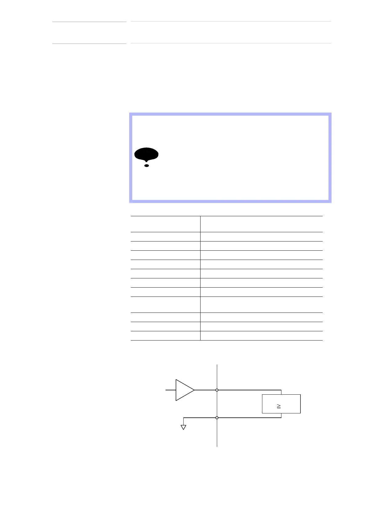
Two analog output circuits (channel 1 for voltage command, and channel
2 for current command) are available.
Fig. 6-1: Example connection
• When connecting a load to the analog output circuit, the
load resistance must be 2 k or more. If the load
resistance is less than 2 k, abnormal output voltage or
damage to the output circuit may result.
• The analog output becomes undefined when the DX200 is
turned on or off. Use an external circuit so that there is no
problem even if the analog output becomes undefined.
• Use shielded twisted-pair wires (24 to 28 AWG) for the
analog output wiring, and make the wiring length as short
as possible.
Number of channels and
application
2 channels for voltage output
Output range -14 V to +14 V
Digital resolution 12 bit
LSB value Approx. 6 mV (0.0068 V)
D/A output voltage error ±14 V, equal to or less than ±1%
Linearity error Equal to or less than ±0.2%
Forward and reverse error Equal to or less than ±1%
Ripple voltage Equal to or less than ±0.1 V
Temperature drift Equal to or less than ±1850 PPM/°C
For 0 V, equal to or less than ±20.5 mV (3 LSB)
Conversion cycle Every communication cycle
Conversion time Approx. 7 ms (including communication time)
External load resistance Equal to or more than 2 k
CH*
YEW01 side
0 V
(Analog ground)
CH*_G
Load
(R 2 kΩ)
L