WFC- SC(H) Series .Installation
- 12 -
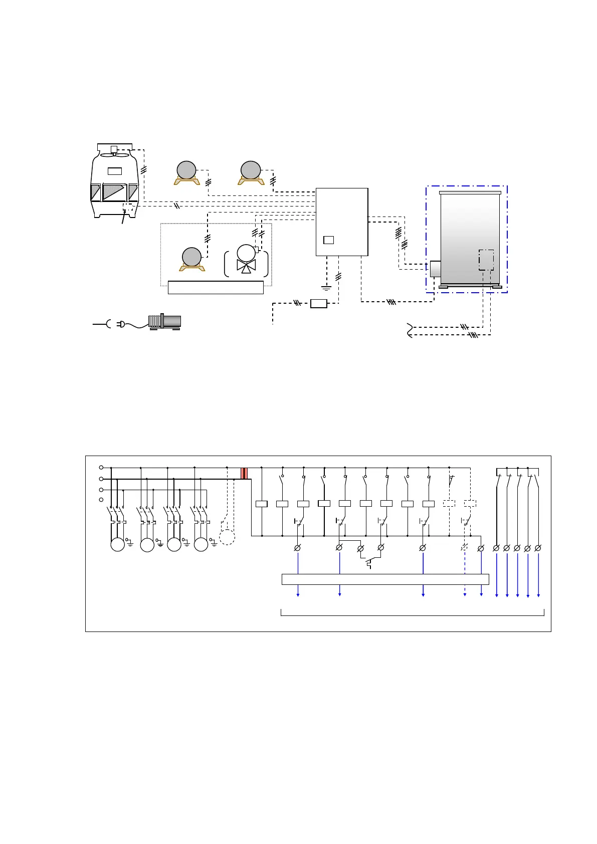
5. Electrical Wiring.
5.1. Electrical system diagram
Figure 5-1-1 illustrates a typical electrical system diagram. Refer following section
for wiring details.
5.2. Electrical connection of auxiliary equipment
All connection according to figure 5-2-1 must be supplied externally by others.
.
Note 1. All conductors must be from copper material.
Note 2. All circuits except power supply are low voltage.
Note 3. All wiring must comply with local and national electrical code and regulation.
Note 4. Cooling water switch (CTS) in sump of cooling tower use switch with maximum contact
rating of 24VAC ,1.2VA(60VA).
Note 5. The symbols shown in Figure 5-2-1 as P,CP,P3A,CM1,3,4,5,6,CM2 are connect to
terminals located in Junction box (section 5-3.).
Note 6.The 3 way valve control can be used in situations where the heat medium pump (P3) is
under separate control
LTM1 is limit switch of 3 way valve.
cooling water
chilled water
cooling tower
fan
heat medium
pump
Note.4
Connect to Junction Box
(Note.5)
In case of using
3 way valve ( Note.6 )
( P3A )
RT1
3way
valve
SW2
SWF
P3A
SW3
SWV
Do not exceed 24VAC,60VA
CM2
RT2 RTF RT3
R
P1
P2
CTF
P3
L1
L2
L3
PE
PEPEPE
PE
THR1
MC1
T HR2
MC2
THRF
MCF
THR3
MC3
Note.6
Figure 5-2-1 (Typical connection )
M
Chilled / Hot
Water Pump
Cooling
Water Pump
Cooling Tower Fan
Absorption Machine
Control Board
Vacuum Pump
Cooling water
Switch
Electrical source
AC400V 3ph 50Hz
Electrical source
AC230V 50Hz 1ph
Over current
breaker
Emergency Switch
Status signal
Remote operation &
C/H mode Changeover
Pump & Fan interlock
Junction box
Internal
Control Box
Pump control
Figure 5-1-1
*1.Exept absorption machine (chain line) must be supplied externally by others.
*2.AC 230V 50Hz 1ph. power consent is required for maintenance (vacuum pump operation).
*3.The 3 way valve control can be used in situations where the heat medium pump (P3) is under
separate control.
*4. Emergency switch (Power shut down switch) must be installed to Control Board.
AC400V 3ph 50Hz
*1
*3
*4
Heat Medium
Pump
*2
3 way Valve
For Heat Medium Control
 Loading...