WFC- SC(H) Series .Installation
- 8 -
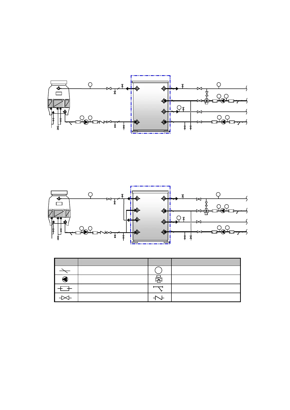
*1.Except absorption machine (chain line) must be supplied externally by others.
*2.The strainer should install upstream of the pump to protect pumps from contamination.
*3.The 3 way valve should be installed where the heat medium pump is under separate control.
*4 and *5. Pressure drop adjust by manual valve and pressure gauge, the pressure drop will not
to change by 3 way valve opening.
*6.Use in case of repairing the components (pumps etc.) or drain the water in winter time etc.
*7.Do not exceed 588 kPa in the water & heat medium circuit!
Figure 10 Typical piping system diagram
WFC-SC30 ,SH30
WFC-SC50
Cooling Tower
P
P
P
P
P
P
Air vent
Air vent
Drain
Chilled water
Heat medium
P
P
for
Chemical
washing
Drain
Air vent
P
for
Chemical
washing
Drain
Water
supply
Cooling water
Cooling Tower
P
P
P
P
P
P
Air vent
Air vent
Drain
Chilled water
Heat medium
P
P
for
Chemical
washing
Drain
Air vent
P
for
Chemical
washing
Water
supply
Cooling water
Symbol
Part name
Symbol
Part name
Thermometer Well
Pressure Gauge ( 0-1.5 MPa )
Circulation Pump
3 way valve
Flexible Joint
Strainer
Manual Valve
Check Valve
*1
*1
*2
*2
*3
*3
*4
*4
*5
*6
*6
*6
*5
*6
Typical piping system diagram
 Loading...