IM 01E21A03-02EN
6
<2. Explosion Protection Type>
6
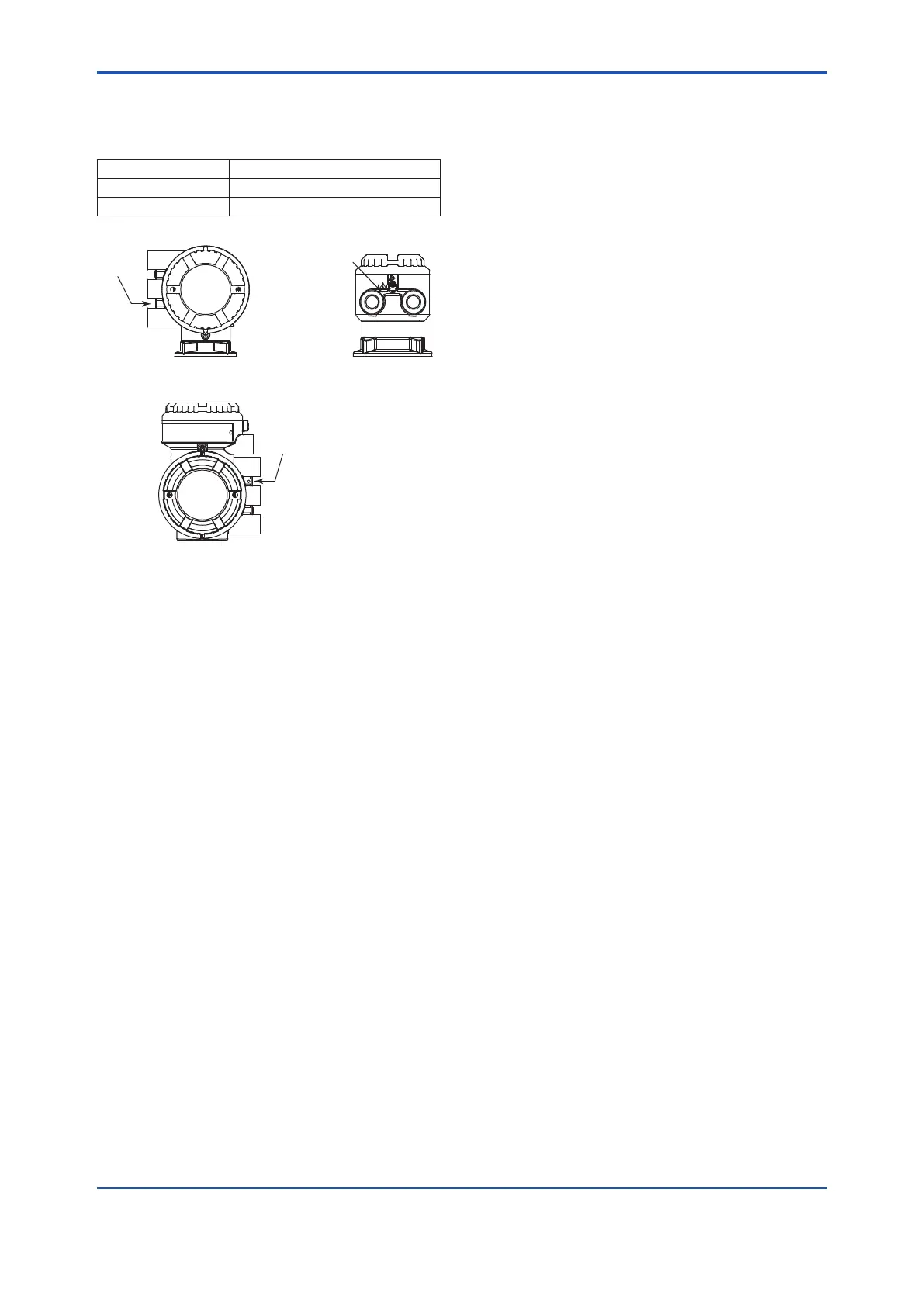
2.2 Cable Entry
The type of cable entry is stamped near the cable
entry port according to the following codes.
Marking Screw Size
M ISO M20 x 1.5 Female
N ASME 1/2 NPT Female
Integral Flowmeter Remote Sensor
Remote Transmitter
2.3 Installation
Read the Installation Manual, IM 01E22A01-01EN
(for AXG### and AXG4A) or IM 01E24A01-01EN
(for AXW### and AXW4A), for basic installation
procedure.
• All wiring shall comply with EN 60079-14, and
local electric codes and requirements.
• Unused apertures shall be closed with suitable
certied blanking elements.
(The plug attached is certied.)
• If the magnetic owmeter is mounted in an area
in the presence of combustible dust, it shall
be installed in such a way that the risk from
electrostatic discharges and propagating brush
discharges caused by rapid ow of dust is avoided.
• The sensor is not surrounded by pipe insulation
material.
• Cable glands, adapters and/or blanking elements
with a suitable IP rating shall be of Ex db IIC/Ex tb
IIIC or Ex eb IIC/Ex tb IIIC certied by ATEX and
shall be installed so as to maintain the specic
degree of protection (IP code) of the product.
• Take care the following warning marking
“POTENTIAL ELECTROSTATIC CHARGING
HAZARD”.
• In order to prevent the grounding conductor from
loosening, the conductor must be secured to the
terminal, tightening the screw with appropriate
torque. Care must be taken not to twist the conductor.
• For multiple types of protection for terminal
compartment, permanently mark the protection
type installed. Once the type is marked, it cannot
be changed.
• If the product is installed as the protection type Ex e,
terminate all the cable nish with crimp terminal of
a rod shape which of conductor length is 5 to 6 mm
and cross section is 0.8 to 2.5 mm
2
, and connect
them reliably.
• For the installation of multi protection type, tick the
box of the selected type of protection type on the
label in order to avoid confusion.
e.g. In the case of selecting “db”, not “eb”
Ex db eb ia IIC T6...T3 Gb
Ex tb IIIC T75°C...T130°C Db
Terminal Compartment: Ex db Ex eb
 Loading...
