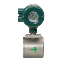
Do you have a question about the YOKOGAWA ADMAG AXR and is the answer not in the manual?
| Brand | YOKOGAWA |
|---|---|
| Model | ADMAG AXR |
| Category | Measuring Instruments |
| Language | English |
Essential safety guidelines for flowmeter operation, covering installation, wiring, and general use.
Details the terms of the instrument's warranty and conditions under which it does not apply.
Information relevant to ATEX certification and documentation for countries in the European Union.
Verifies the model code and specifications against the ordered product using the nameplate.
Guidelines for storing the instrument for extended periods to maintain its condition and performance.
Selects installation locations considering ambient temperature, atmospheric conditions, and vibrations for stable operation.
Critical precautions for designing piping to prevent flowtube damage and ensure accurate measurement.
Important handling aspects during installation, including general precautions and impact avoidance.
Step-by-step guide for mounting the flowmeter, including torque values and centering devices.
Specific mounting steps for wafer type flowmeters of specified sizes, including bolt tightening.
Specific mounting steps for wafer type flowmeters of larger sizes, including bolt tightening procedures.
Specific mounting steps for flange type flowmeters, including bolt tightening procedures.
Details gasket dimensions to prevent protrusion into piping and ensure proper sealing.
Essential precautions for safe and correct wiring, including cable connection and conduit use.
Guidance on using wiring ports, including sealing caps and waterproof glands for protection.
Critical grounding requirements for instrument safety and accurate flow measurement.
Procedures for accessing and connecting wiring within the terminal box, including cover removal.
Step-by-step guide for connecting power supply, current output, and digital outputs correctly.
Overview of the display unit's configuration, functions, and the operation of its switches.
Describes how to navigate and change settings on the display unit.
Procedure for transitioning from the normal display mode to the setting mode for parameter adjustments.
General procedure for setting parameters, including examples for different data types.
Demonstrates setting flow rate units using a selection-type parameter via the display unit.
Demonstrates setting flow rate span using a numeric-type parameter via the display unit.
Demonstrates setting the tag number using an alphanumeric-type parameter via the display unit.
Introduces the instrument's internal parameters and their initial default values.
Explains the structure and items included in the parameter lists for configuration.
Provides an overview of parameters organized into menus (A, B, C, D, E, F, G, H, J, K, M, N, P).
Detailed explanation of various parameters, including language, flow damping, units, and span settings.
Details alarm classifications, selection methods, and specific alarm parameters.
Classifies alarms into four levels: System, Process, Setting, and Warning.
Explains how specific alarms are recognized and configured through parameter settings.
Lists system and process alarms, their descriptions, and corresponding countermeasures.
Describes the NE-107 status categories for alarms and their device status implications.
Covers the fundamental operations of the BT200 handheld terminal.
Details the physical layout of the BT200's keys and display screen.
Explains the function of each key, including alphanumeric and function keys.
Describes how to use the BT200 for operating the AXR flowmeter.
Details the procedure for connecting the BT200 to the AXR's signal line.
Explains how to update, upload, and download data using the BT200.
Guides on navigating BT200 screens to display flow rate data.
Provides procedures for setting parameters on the AXR using the BT200.
Demonstrates setting flow rate units using a selection-type parameter via the display unit.
Demonstrates setting flow rate span using a numeric-type parameter via the display unit.
Demonstrates setting the tag number using an alphanumeric-type parameter via the display unit.
Explains how to confirm and manage HART protocol revisions for HART 5.
Essential steps to confirm DD and device revisions before using HART tools.
Procedures to verify DD and device revisions for compatibility with HART tools.
Details how to connect the AXR to a HART configuration tool for communication.
Covers initial confirmation and changes to tag and device information within the HART tool.
Describes the hierarchical structure of parameters accessible via the HART configuration tool.
Explains methods for loading AXR data to/from HART tools.
How to run self-diagnostics on the AXR using DD and DTM.
Covers advanced HART functions like trimming, fixed output, and burst mode.
Procedure to adjust analog output signals (4 mA and 20 mA) using D/A trim.
Feature to output a fixed current for loop checks.
Configuration for the transmitter to continuously send data via HART.
Setting up multidrop communication for connecting multiple transmitters.
Procedure to switch between HART protocol revisions 5 and 7.
Refers to the HART configuration tool operations manual for additional functions.
Provides a hierarchical view of parameters accessible via DD for HART 5.
Explains how to confirm and manage HART protocol revisions for HART 7.
Essential steps to confirm DD and device revisions before using HART 7 tools.
Procedures to verify DD and device revisions for HART 7 compatibility.
Details how to connect the AXR to a HART 7 configuration tool.
Covers initial confirmation and changes to tag and device information within the HART 7 tool.
Describes the hierarchical structure of parameters accessible via the HART 7 configuration tool.
Explains methods for loading AXR data to/from HART 7 tools.
How to run self-diagnostics on the AXR using DD and DTM for HART 7.
Covers advanced HART 7 functions like test output, simulation, and squawk.
Details test output, simulation, and squawk functions for HART 7.
Procedure to adjust analog output signals using D/A trim with HART 7.
Configuration for transmitting data via HART 7 in burst mode.
Setting up multidrop communication for HART 7.
Procedure to switch between HART protocol revisions 5 and 7.
Provides a hierarchical view of parameters accessible via DD and DTM for HART 7.
Essential procedure to perform before actual operation to ensure accurate zero flow output.
Detailed steps for performing zero adjustment using display unit switches or external status input.
Procedure for changing the orientation of the electrical connection converter.
Guidelines for replacing internal components like the display unit and amplifier assembly.
Steps for safely removing and replacing the display unit.
Steps for safely removing and replacing the amplifier assembly.
Explains how to set the burnout and write protect switches.
Details how to set the burnout switch for output direction under system alarms.
Explains how to use hardware or software settings to prevent parameter overwrites.
Describes a function to check electrode adhesion by measuring resistance.
Lists routine inspection tasks for the terminal box and piping joints.
Procedures for performing insulation resistance and dielectric strength tests.
Step-by-step guide for conducting the insulation resistance test.
Step-by-step guide for conducting the dielectric strength test.
Provides guidance for identifying and resolving common instrument issues.
Troubleshooting steps for situations where no indication is displayed on the converter.
Troubleshooting steps for issues related to unstable zero readings or output fluctuations.
Troubleshooting steps for discrepancies between displayed and actual flow readings.
Key technical specifications of the AXR flowmeter, including converter and flowtube details.
Classification of hazardous areas according to ATEX and other standards.
Details accuracy, repeatability, and performance under calibrated conditions.
Specifies acceptable ambient temperature, humidity, fluid conductivity, and operating ranges.
Explains how to interpret model and suffix codes for ordering and identification.
Provides dimensional drawings and specifications for various flowtube types and lay lengths.
Technical data and specifications for ATEX certified explosion-proof instruments.
Technical data and installation requirements for FM certified explosion-proof instruments.
Technical data and installation requirements for CSA certified explosion-proof instruments.
Technical data and specifications for IECEx certified explosion-proof instruments.
Technical data and precautions for TIIS flameproof instruments.
Overview of user responsibilities for SIS installation and operation.
Guidelines for applying the AXR within Safety Instrumented Systems (SIS).
Critical parameters that must be set to maintain safety integrity in SIS applications.
Procedures and methods for proof testing to detect flowmeter failures in SIS.
Procedures for repairing or replacing the AXR, including bypass requirements.
Details on failure mode analysis and reliability data for AXR in SIS.
Glossary of terms and abbreviations used in the appendix.


