12-1
IM 01E30D01-01EN
<12. OUTLINE>
12.1 STANDARD
SPECIFICATIONS
Converter
The contents of (*1) and (*2) described in the
converterspecicationsarefollows.
*1: One output can be selected from pulse, alarm, or
status through the parameter setting.
*2: For models without an indicator, the con-
gurationtool(Suchashandheldterminalor
FieldMate, etc.) is necessary to set or change
parameters.
Excitation Method:
•Dualfrequencyexcitation:Size25to200mm(1to
8 in.)
Output Signals:
Current output and digital output can be carried out
simultaneously.
Read Section 4.6.
•Currentoutput:4to20mADC,two-wiresystem
Output range: 3.8 to 20.5 mA (–1.25 to 103.13%)
•Digitaloutput(*1):
Transistor contact output, open collector
Contact rating: 30 V DC, 120 mA DC
Low level: 0 to 2 V DC (Read Figure 12.1)
HIGH level
LOW level
0 V
0 to 2 V
F1201.ai
Figure 12.1 High and Low levels
(transistor contact output)
Current Output Status at System Alarms (Burnout)
Up-scale: 110%, 21.6 mA DC or more (standard)
Down-scale: –5%, 3.2 mA DC or less
Supply Voltage:
14.7 to 42 V DC for general-purpose use and explo-
sion proof type
14.7 to 32 V DC for lightning protector
(optional code A)
Note 1: Supply voltage means the voltage necessary to pro-
vide between the power terminals of the magnetic
owmeter.
Note 2: Connecting with the commercial AC power supply
willdamagetheowmeter.BesuretousetheDC
power supply in the predetermined range.
Note3:TheADMAGAXRcanbeconnectedwithalmost
all distributors, signal conditioner cards, and I/O
modules except certain devices.
Read the following table for Yokogawa’s devices,
choose an appropriate connecting device and the
corresponding length of cable.
For devices other than those in the table, decide on
theconnectionbyreadingthesupplyvoltagespeci-
cations and the description in Section 4.6.
Connecting device
Maximum length of cable
(rough guideline)
Name Model
Cable with
cross section
of 2 mm
2
Cable with
cross section
of 1.25 mm
2
Signal
Conditioner
Card
EA1
EA2
2 km 2 km
I/O Module
AAM11
AAM11B
2 km 2 km
Analog I/O
Module
(for FIO)
AAI143 2 km 2 km
AAI141
AAI841
AAI135
AAI835
Not applicable Not applicable
Analog I/O
Module (for
Prosafe-RS)
SAI143 1.4 km 0.8 km
Distributor
SDBT
SDBS
2 km 2 km
JUXTA
VJA1
VJA4
VJA7
2 km 2 km
Communication Requirement:
BRAIN
Communication Signal:
BRAIN communication signal (superimposed on 4 to
20 mA DC signals)
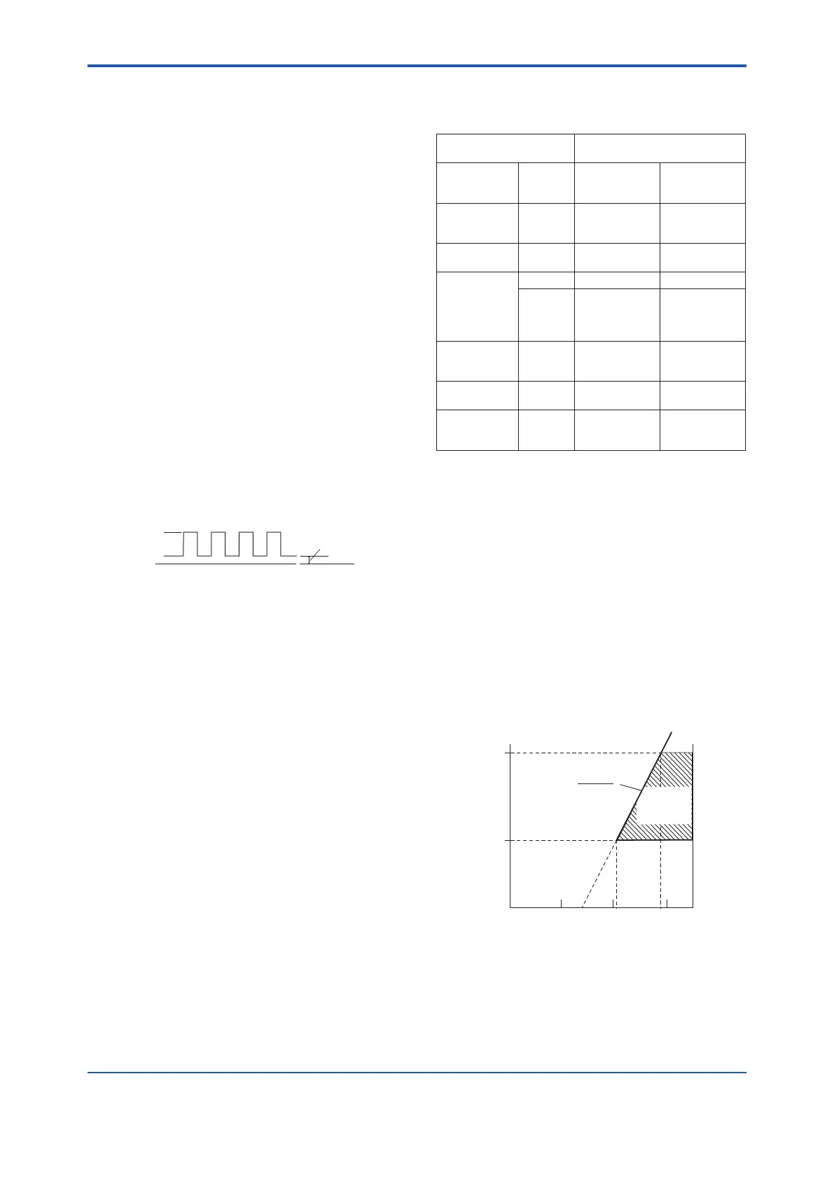
Conditions of Communication Line:
Supply Voltage: 20.6 to 42 V DC
LoadResistance:250to600Ω(includingcable
resistance)
Read Figure 12.2.
Communication Distance: Up to a distance of 2 km
when a CEV cable is used
Read Section 4.6.
LoadCapacitance:0.22μForless
Load Inductance: 3.3 mH or less
Distance from other Power Line: 15 cm (6 in.) or
more (Avoid parallel wiring.)
Input Impedance of Communicating Device:
10kΩormoreat2.4kHz
600
250
14.7 20.6 28.9 42
Power supply voltage E (V DC)
R=
0.0236
E−14.7
Digital
Communication
Range
(BRAIN or HART)
External
Load
Resistance
R (Ω)
Figure 12.2 Relationship Between Power Supply Volt-
age And External Load Resistance
12. OUTLINE

 Loading...


