<11. MAINTENANCE>
11-5
IM 01E30D01-01EN
11.3 Setting of Switches
11.3.1 Setting of Burnout Switch
The burnout function sets the direction of current
output in situations during occurring the system
alarm. Upon shipment from the manufacturing
plant, the burnout direction is set to High (21.6 mA
or more); however, in cases where the optional
codeC1hasbeenspecied,theoutputdirection
will be set to Low (3.2 mA or less).
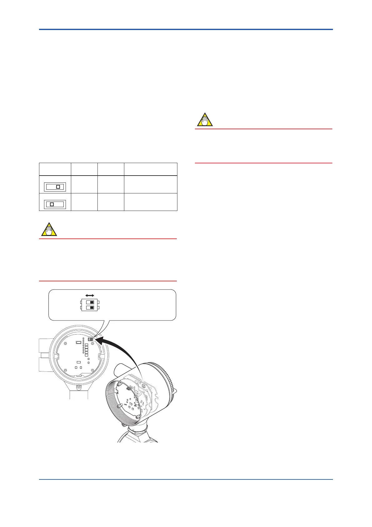
Modicationoftheburnoutdirectionmustbecarried
outusingthesettingswitchfromtheamplier’s
board (Switch 2) (Read Figure 11.3).
Table 11.3 Output Setting Pins for Burnout
Position of
Pin
Burnout
Direction
Burnout
Output
Remarks
L H
High
21.6 mA
or more
Set to High before
shipment
L H
Low
3.2 mA
or less
Set to Low for optional
code C1
NOTE
Ontheamplier’sboard,theburnoutsetting
switch (Switch 2) and the write protect switch
(Switch 1) are located adjacent to each other.
Accordingly, special care should be taken when
making switch settings.
Switch 2
Switch 1
EnableProtect
L H
1 2
ON
F1108.ai
BO
←
Burnout setting switch
WR
←
Write protect setting switch
Figure11.3 SwitchConguration
11.3.2 Setting of Write Protect Switch
By setting the write protect function to “Protect” it is
possible to prevent the overwriting of parameters.
Write protection can be carried out using either the
hardwareswitchontheamplierboard(Switch1)or
software parameter settings. If either of these items
is set to “Protect,” the overwriting of parameters will
be prohibited.
NOTE
If the hardware switch is set to “Protect,” it
will not be possible to overwrite parameters;
furthermore, this condition will be maintained
until the switch is set to “Enable.”
For more details regarding usage of the write
protect function and the software’s parameter
switches, read Chapter 6.

 Loading...


