<4. WIRING>
4-6
IM 01E30D01-01EN
4.5 Wiring Connections
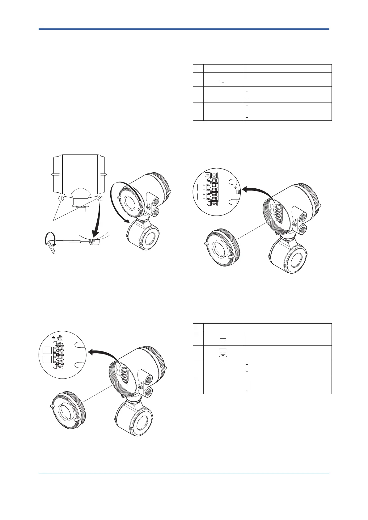
(1) Removing Cover
The cover has the locking screws in front and
behind it as shown in Figure 4.5.1 in case of
explosion proof type. This is used for the cover-
lock system. Loosen cover locking screws
clockwise using a hexagonal wrench (nominal size
3) to unlock the cover. (Upon shipment from the
manufacturing plant, the cover is unlocked.)
Holdtheowmeterwithyourhandandremovethe
cover by turning it in the direction of the arrow as
shown below (both explosion proof and general
purpose types).
F0411.ai
Cover locking
screws
Explosion proof type Both Explosion proof and
General purpose types
Figure 4.5.1 Removing the Terminal Box Cover
(2) TerminalConguration(General-purpose
Use/ExplosionProofTypeexceptTIIS)
When the cover is removed, the connection
terminals will be visible.
SUPPLY
DO
+
−
+
−
➂
➃
➄
➀
➁
Figure4.5.2 TerminalConguration
The description of the terminal symbols is shown in
Table 4.5.1.
Table 4.5.1 Terminal Symbols
No. Terminal Symbols Description
➀
Functional grounding
➁
➂
+
–
SUPPLY
Power supply and current output
➃
➄
+
–
DO
Digital output (One output can be selected
from pulse, alarm or status outputs.)
(3) TerminalConguration(TIISExplosion
Proof Type)
When the cover is removed, the connection
terminal will be visible.
SUPPLY
DO
➀
➂
➃
➄
➁
➅
Figure4.5.3 TerminalConguration
The description of the terminal symbols is shown in
Table 4.5.2.
Table 4.5.2 Terminal Symbols
No. Terminal Symbols Description
➀
Functional grounding
➁
Class A grounding
➂
➃
+
–
SUPPLY
Power supply and current output
➄
➅
+
–
DO
Digital output (One output can be selected
from pulse, alarm or status outputs.)

 Loading...


