<4. WIRING>
4-7
IM 01E30D01-01EN
4.6 Wiring Procedure
(1) Power supply and Current output
This instrument uses the same two wires for both,
the signal and power supply. A DC power supply is
required in a transmission loop.
The allowable power supply voltage is described
below.
• 14.7to42VDCforgeneral-purposeuseand
explosion proof type
• 14.7to32VDCforlightningProtector(optional
code A)
WiretheAXRaccordingtoFigure4.6.1orFigure
4.6.2.
WARNING
Before wiring with external instruments, be sure
to turn off the external instruments.
IMPORTANT
This instrument normally outputs a current of 12
mA for several seconds just after turning on the
power.
Warm up this instrument for at least 30 minutes.
Perform flow measurement 30 minutes after
turning on the power.
SUPPLY
DO
cable
Figure 4.6.1 Electric Cable Wiring (General -
purposeUse/ExplosionProofType
except TIIS)
SUPPLY
DO
cable
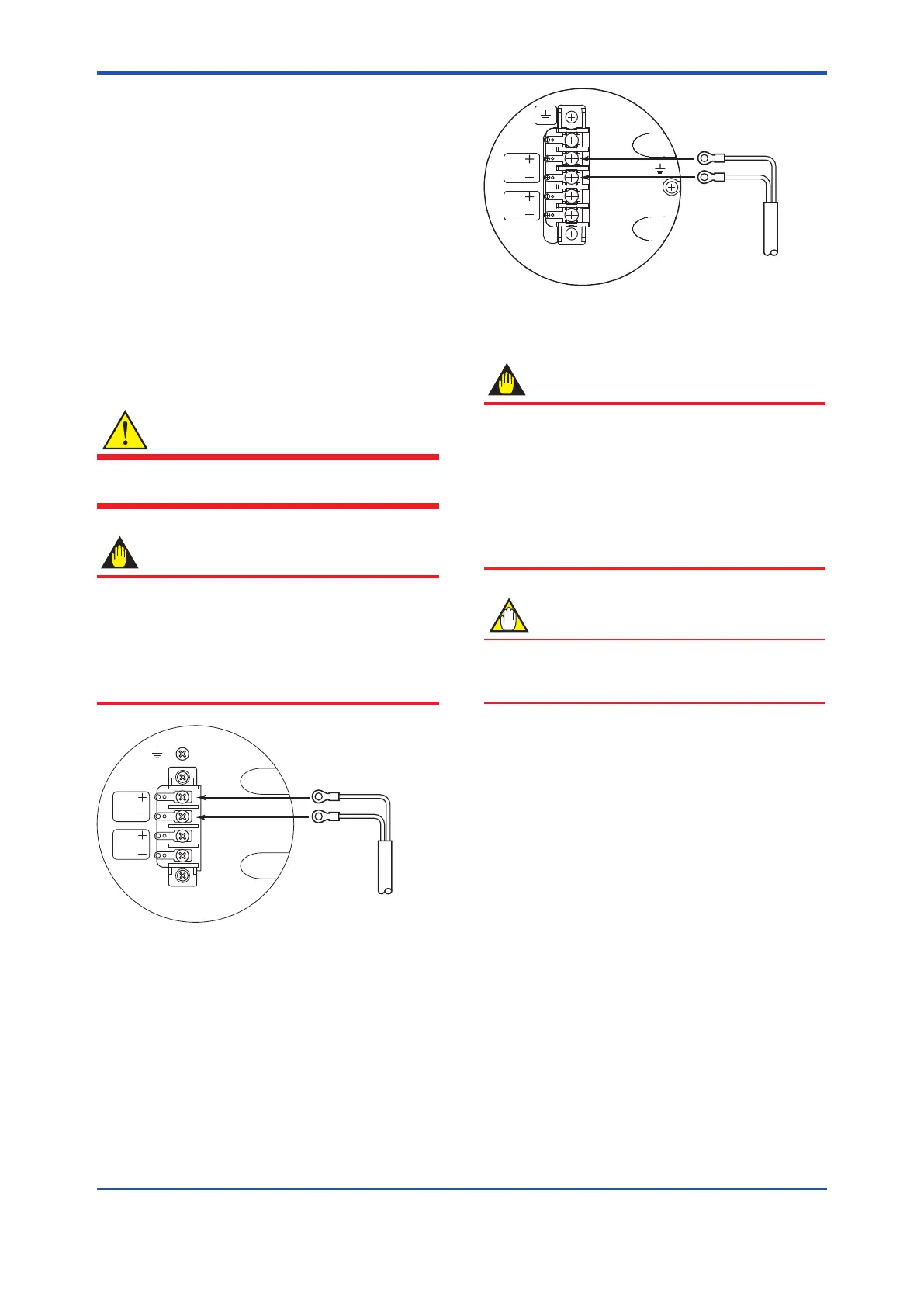
Figure 4.6.2 Electric Cable Wiring (TIIS Explosion
Proof Type)
IMPORTANT
• ConnectingwiththecommercialAXR
powersupplywilldamagetheowmeter.
Be sure to use the DC power supply in the
predetermined range.
• Donotconnectpowersupplywithreversed
polarities.
SUPPLY + terminal: connect +
SUPPLY - terminal: connect -
NOTE
Supply voltage means the voltage necessary
to provide between the power terminals of the
magneticowmeter.
Read Table 4.6.2 to Table 4.6.4 for wiring examples
in case of general - purpose use/explosion proof
type except TIIS.
Read Table 4.6.5 to Table 4.6.7 for wiring examples
in case of TIIS explosion proof type.
TheADMAGAXRcanbeconnectedwithalmost
all distributors, signal conditioner cards, and I/O
modules except certain devices.
Read the Table 4.6.1 for Yokogawa’s devices,
choose an appropriate connecting device and the
corresponding length of cable.
For devices other than Table 4.6.1, decide on
the connection by reading the supply voltage
specicationsandthedescriptionofwiring
examples as shown in Table 4.6.2 to Table 4.6.7.

 Loading...


