12-8
IM 01E30D01-01EN
<12. OUTLINE>
12.4 NORMAL OPERATING
CONDITIONS
Ambient Temperature:
General-purpose Use:
–40 to +55°C (–40 to +131°F)
Explosion proof type:
In the case of explosion proof type, read descrip-
tion of “ Ambient Temperature” “Enclosure” in
“HAZARDOUS AREA CLASSIFICATION”
*1: Minimum temperature should also be limited according
tominimumuidtemperatureofowtube’sspecica-
tion.
Read description of “Fluid Temperature and Pressure”.
*2: Indicator operating range: –20 to +55°C (–4 to +131°F)
Ambient Humidity: 0 to 100%
Lengthy continuous operation at 95% or more is not
recommended.
Fluid Conductivity:
Size25to200mm(1to8in.):10μS/cmorlarger
Note: Fluidswithlargeownoise(purewater,uidswith
low conductivity and low viscosity such as alcohol)
causetheoutputuctuationandthereforeitisimpos-
sible to measure accurately.
Output Fluctuation:
Theoutputuctuatesdependingontheuidcondi-
tions and damping settings.
Thefollowingtableshowstheoutputuctuationas
aroughguidelineatowvelocitynear100%ofow
span (damping: 5 s)
•Size25to100mm(1to4in.)
Fluid
Conductivity
[μS/cm]
Fluctuation (% of rate) as a rough guideline
Flow Span
2.0m/s
Flow Span
4.0m/s
10 3.0% or less 7.0% or less
50 1.0% or less 1.0% or less
100 0.5% or less 0.5% or less
500 0.5% or less 0.5% or less
•Size150to200mm(6to8in.)
Fluid
Conductivity
[μS/cm]
Fluctuation (% of rate) as a rough guideline
Flow Span
2.0m/s
Flow Span
4.0m/s
10 5.0% or less Non-recommendation
50 2.0% or less 3.0% or less
100 1.0% or less 1.0% or less
500 0.6% or less 1.0% or less
Measurable Flow Rate Range:
SI Units (Size: mm, Flow rate: m
3
/h)
Size
(mm)
0 to Min. Span Flow
Rate(0.3m/s)
0 to Max. Span Flow
Rate(10m/s)
25 0 to 0.5302 m
3
/h 0 to 17.671 m
3
/h
40 0 to 1.3572 0 to 45.23
50 0 to 2.1206 0 to 70.68
65 0 to 3.584 0 to 119.45
80 0 to 5.429 0 to 180.95
100 0 to 8.483 0 to 282.74
150 0 to 19.090 0 to 636.1
200 0 to 33.930 0 to 1,130.9
English Units (Size: in., Flow rate: GPM)
Size
(in.)
0 to Min. Span Flow
Rate(1ft/s)
0 to Max. Span Flow
Rate(33ft/s)
1.0 0 to 2.335 GPM 0 to 77.80 GPM
1.5 0 to 5.253 0 to 175.0
2.0 0 to 9.337 0 to 311.2
2.5 0 to 14.59 0 to 486.2
3.0 0 to 21.01 0 to 700.2
4.0 0 to 37.35 0 to 1244
6.0 0 to 84.03 0 to 2800
8.0 0 to 149.4 0 to 4979
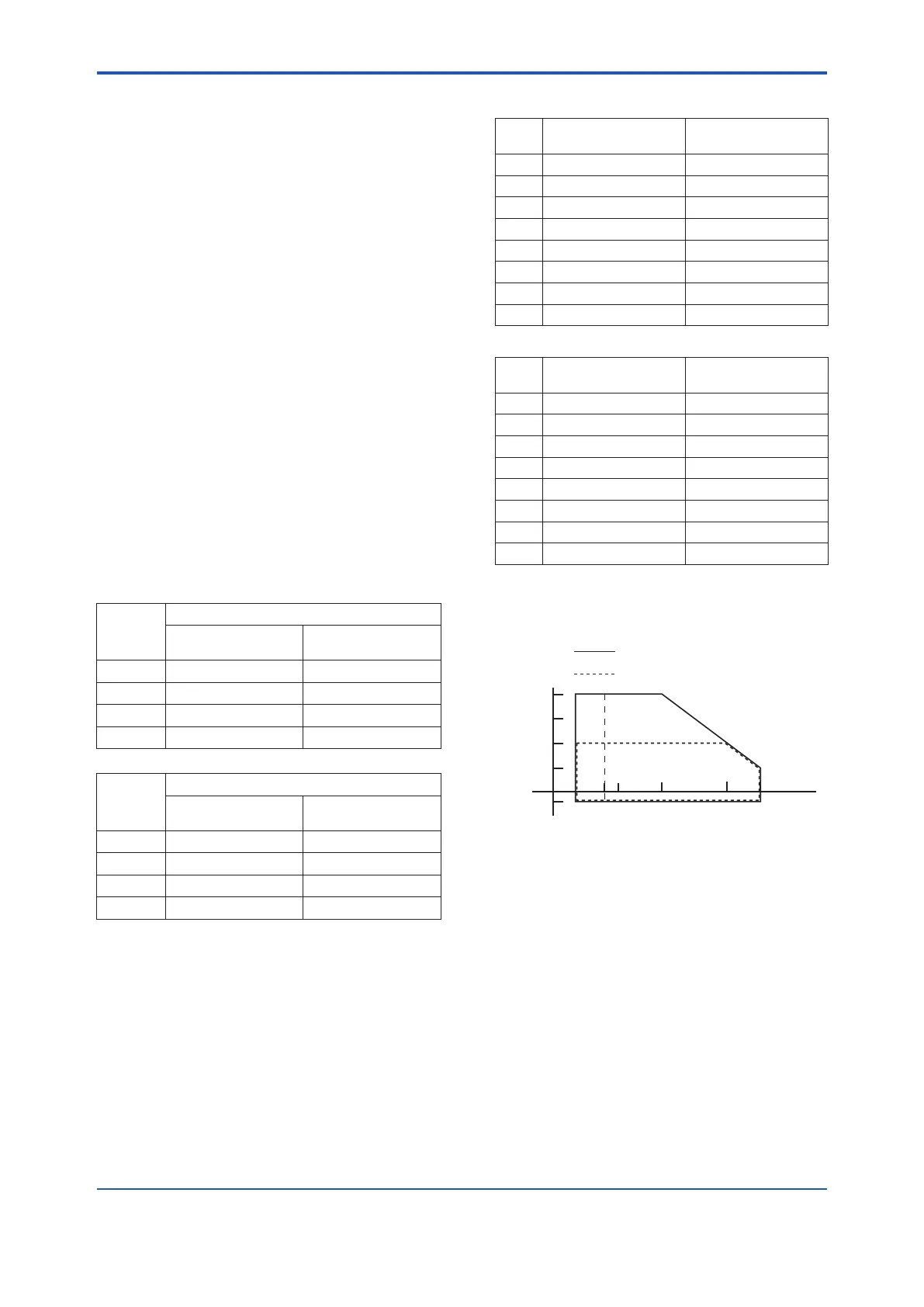
Fluid Temperature and Pressure:
Thefollowinggureshowsmaximumallowableuid
pressurefortheowtube.Furtheruidpressure
shouldalsobelimitedaccordingtoangerating.
F1206.ai
25 to 50 mm (1.0 to 2.0 in.)
(flange type, wafer type)
65 to 200 mm (2.5 to 8.0 in.)
(flange type, wafer type)
Pressure
MPa (psi)
4 (580)
2 (290)
1 (145)
−
0.1 (-14.5)
−40
(-40)
0
(32)
40
(104)
100
(212)
Temperature °C (°F)
−10
(14)
130
(266)
*1
*1: For wafer types of 40 to 200 mm (1.5 to 8.0 in.), and for
carbonsteelangetypes(processconnectioncode:
C**)of150to200mm(6.0to8.0in.),theminimumuid
temperature is –10°C (+14°F).
*2: Foruidtemperatureoftheexplosionprooftype,read
descriptions of “HAZARDOUS AREA CLASSIFICA-
TION”.
Vibration Conditions:
9.8 m/s
2
or less (frequency of 500 Hz or less)
Note: · Level of vibration is in conformity with IEC 60068-2-6
(SAMA 31.1-1980).
· Avoid locations with much vibration where the pipe
vibration frequency is 500 Hz or more. Such a condi-
tion may cause damage to the instrument.

 Loading...


