<3. INSTALLATION>
3-10
IM 01E30D01-01EN
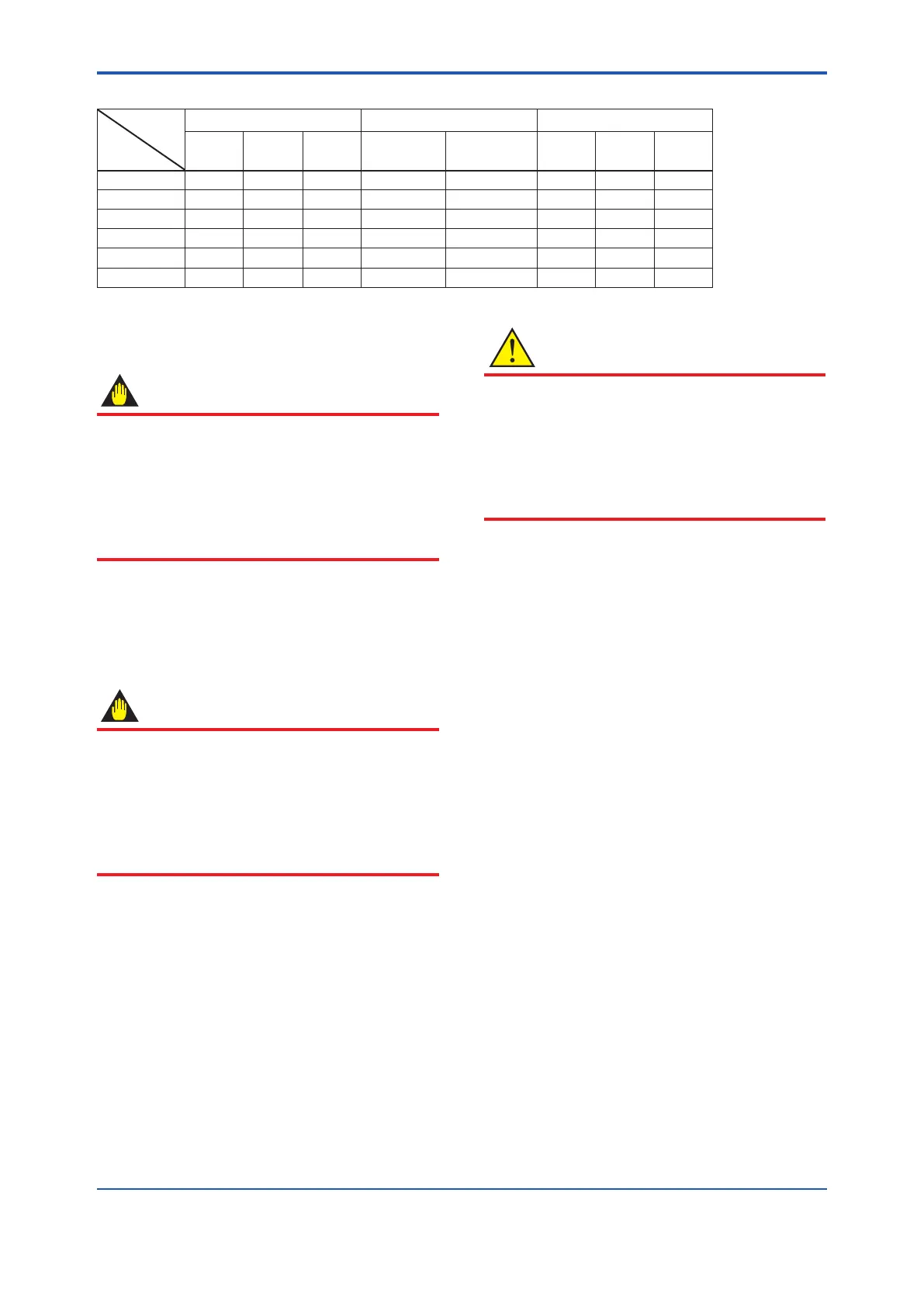
Table3.3.8 CenteringDeviceIdentication(AXRLaylengthcode2,PFAlining)
Flange
ratings
Size
mm (inch)
JIS ANSI DIN
10K 20K
F12
(75M)
150 300 PN10 PN16 PN40
50 (2.0) B B — B F — — F
65 (2.5) B B — B G — F —
80 (3.0) B F H F C — G —
100 (4.0) B F H C H — F —
150 (6.0) C D D C E — C —
200 (8.0) C D D D E C C —
*:Eachcenteringdeviceisengravedwithacharacterasidentication.
3.3.3 Nominal Diameter 25 mm (1.0 in.) to
200 mm (8.0 in.), Flange Type
IMPORTANT
Useboltsandnutsincompliancewiththeange
ratings. Be sure to choose a gasket with inner
and outer diameters that does not protrude
inside the piping (Read Subsection 3.3.4). If the
inner diameter of the gasket is too large, or outer
diameterofthegasketistoosmall,uidleakage
may result.
(1) Mounting Direction
Mounttheowmetersothattheowdirectionofthe
uidtobemeasuredisinlinewiththedirectionof
thearrowmarkontheowmeter.
IMPORTANT
If it is impossible to match the direction of
the arrow mark, the direction of the electrical
connection can be changed. Read Section 11.1
to do this properly.
Incasetheuidbeingmeasuredowsagainst
the arrow direction, read the parameter J20:
Flow Direction in this user’s manual.
(2) Tightening Nuts
Tighten the bolts according to the torque values
for the metal piping in Table 3.3.9. For PVC piping,
select an optional code of GA, GC, or GD, use
rubber gaskets and tighten the nuts to the torque
values for the PVC piping in Table 3.3.10.
Forpermeableuids(suchasnitricacid,
hydrouoricacid,orsodiumhydrateathigh
temperatures), tighten the nuts according to the
torque values in Table 3.3.11.
CAUTION
ForaowmeterwithuorocarbonPFAlining,
it is possible that the nuts may loosen as time
passes, so tighten them regularly. Be sure to
tighten the nuts according to the prescribed
torque values. Tighten them diagonally with
the same torque values, step by step up to the
prescribed torque value.

 Loading...


