24
IM 12D06D05-01E
5-6. mA output setup
The general procedure is to first define the
function (control, output, simulate, off) of the
output and second the process parameter
associated to the output. Available process
parametersdependonselected“sensortype”
and“measurementsetup”.
Off :Whenanoutputissetoffthe
output is not used and will give an
outputof4mA.
Control : A selection of P- PI- or PID control
Manual :Staticoutputrequiredtomaintain
reset equilibrium state with setpoint.
Direction : Direct
If the process variable is too high
relativetotheSP,theoutputof
the controller is increased (direct
action).
: Reverse
If the process variable is too high
relativetotheSP,theoutputofthe
controller is decreased (reverse
action).
Output :
Linearornonlineartableoutput.
The table function allows the configu-
ration of an output curve by 21 steps
(5%intervals).Inthemainmenu
concentration can be selected to set
the concentration range.
Simulate :Percentageofoutputspan.
Normal span of outputs are limited
from 3.8 to 20.5 mA
Failsafe :ContactS4isprogrammedasa
fail-safe contact.
BurnLoworHighwillgiveanoutputof3.6
resp.21mAincaseofFailsituation.
Note! When leaving Commissioning, Hold
remains active until switched off
manually. This is to avoid inappropriate
actions while setting up the
measurement.
Proportional control
Proportional Control action produces an output
signal that is proportional to the difference
betweentheSetpointandthePV(deviationor
error). Proportional control amplifies the error to
motivate the process value towards the desired
setpoint. The output signal is represented as a
percentageofoutput(0-100%).
Proportional control will reduce but not
eliminate the steady state error. Therefore,
proportional Control action includes a Manual
Reset. The manual reset (percentage of output)
is used to eliminate the steady state error.
Note! Any changes (disturbances) in the
process will re-introduce a steady state
error.
Proportional control can also produce exces-
sive overshoot and oscillation. Too much gain
may result in an unstable- or oscillating proc-
ess. Too little gain results in a sustained steady
state error. Gain = 1/Range. [PV units]
Integral Control
Integral control is used to eliminate the steady
state error and any future process changes.
It will accumulate setpoint and process (load)
changes by continuing to adjust the output
untiltheerroriseliminated.Smallvaluesof
integral term (I-time in seconds) provide quick
compensation,butincreaseovershoot.Usually,
the integral term is set to a maximum value that
provides a compromise between the three sys-
tem characteristics of: overshoot, settling time,
and the time necessary to cancel the effects of
static loading (process changes). The integral
term is provided with an anti windup function.
When the output of PI portion of the controller
isoutsidethecontrolrange(lessthan-5%or
greaterthan105%),theI-partisfrozen.
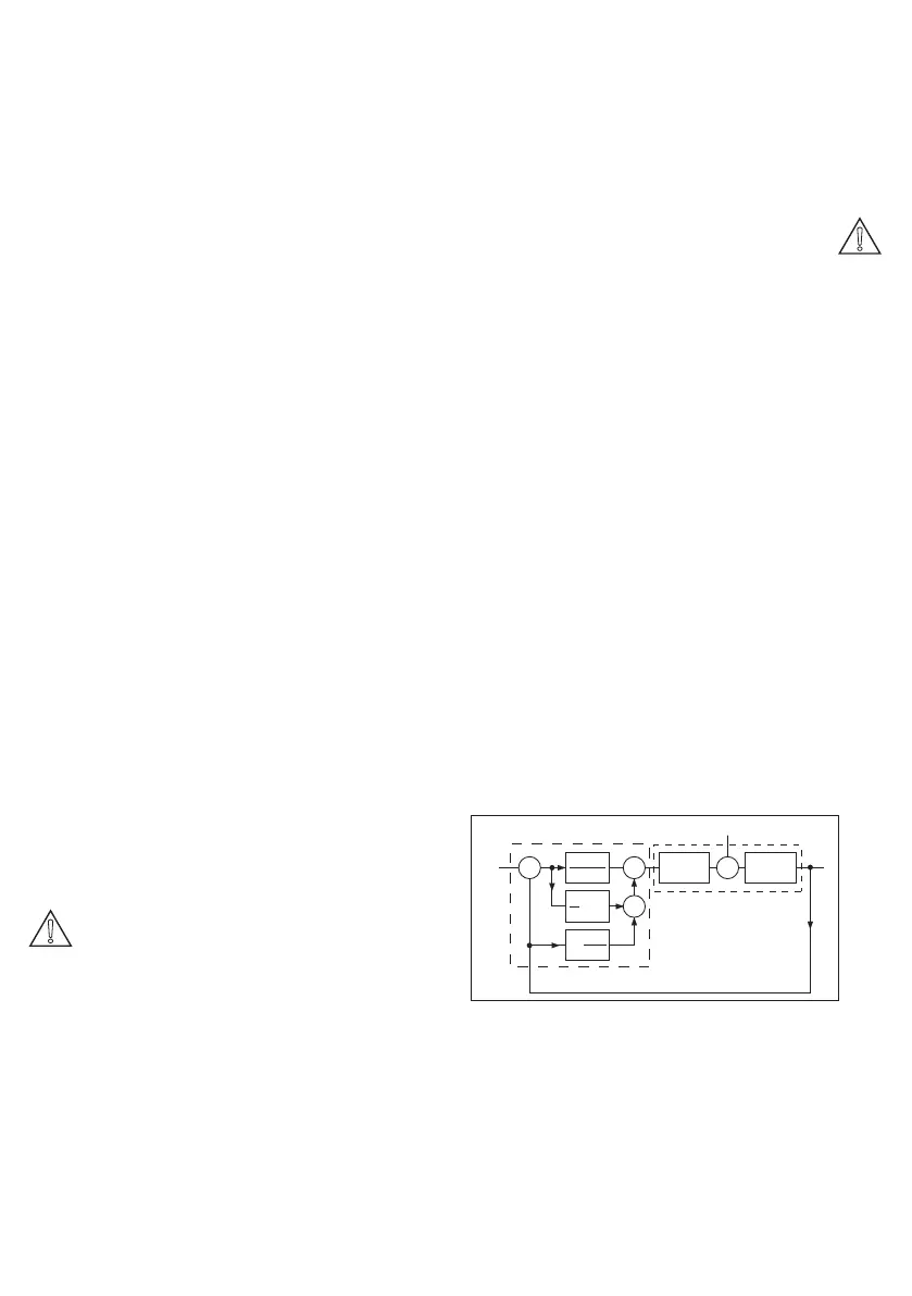
SP
PV
e
+
-
+
+
+
+
+
-
e
Range
ºe dt
1
T
i
T
d
dPV
dt
Process
Controller
Actuator
Process
Figure 5-1. Control Diagram
Derivative control
The control acts on the slope (rate of change)
of the process value, thereby minimizing
overshoot.Itprovides“rate”feedback,resulting
in more damping. High derivative gains can
increase the rizing time and settling time. It is
difficult to realize in practice because differen-
tiationleadsto“noisy”signals.
 Loading...

