43
IM 12D06D05-01E
9
QUALITYINSPECTION
9. QUALITY INSPECTION
Quality
Inspection
Standards
ISC450G
Inductive Conductivity Converter
QIS 12D06D05-01E
1st Edition: Jul. 2007
1. Scope
This inspection standard applies to the ISC450G Inductive Conductivity Converter.
2. Inspection Items
2.1 Insulation resistance test
*2.2 Dielectric strength test
*2.3 Sensor signal input test
2.4 Temperature indication check
2.5 Current output test
Note: Items marked with an asterisk (*) may only be confirmed by a test certificate.
3. Inspection Methods, Standards and Conditions
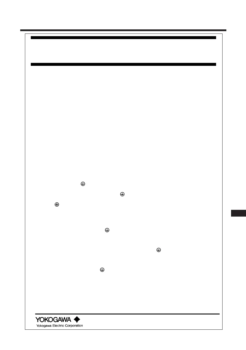
z Connect the testing circuit as shown in Figure 1. Allow the instrument to warm up for
at least 5 minutes before conducting the tests. For the connections for the insulation
resistance and dielectric strength tests, follow the instructions in Sections 3.1 and 3.2.
3.1 Insulation Resistance Test
Apply 500 V DC between the terminals shown below. The insulation resistance must be
100 MΩ or greater.
(1) Between the power supply terminals shorted together (1 and 2) and the protective
earth terminal (
)
(2) Between the contact output terminals shorted together (32, 33, 42, 43, 52, 53, 72 and
73) and the protective earth terminal (
)
(3) Between the current output terminals shorted (62) and the protective earth terminal
(
)
3.2 Dielectric Strength Test
(1) Apply 1390 V AC, an AC voltage of substantially sinusoidal waveform with a frequency
of 50 Hz or 60 Hz, between the power supply terminals shorted together (1 and 2) and
the protective earth terminal (
), for at least 2 seconds. The insulation must withstand
this voltage. (The sensed current should be 10 mA.)
(2) Apply 1390 V AC, an AC voltage of substantially sinusoidal waveform with a frequency
of 50 Hz or 60 Hz, between the contact output terminals shorted together (32, 33, 42,
43, 52, 53, 72 and 73) and the protective earth terminal (
), for at least 2 seconds.
The insulation must withstand this voltage. (The sensed current should be 10 mA.)
(3) Apply 500 V AC, an AC voltage of substantially sinusoidal waveform with a frequency
of 50 Hz or 60 Hz, between the current output terminals shorted (62) and the
protective earth terminal (
), for at least 2 seconds. The insulation must withstand
this voltage. (The sensed current should be 10 mA.)
3.3 Sensor Signal Input Test
Connect the testing circuit as shown in Figure 1 and set the equipment as follows:
Decade resistance box 1 (temperature simulation input): 1097.3 [Ω]
Decade resistance box 2 (conductivity simulation input): 150 [Ω]
The power supply voltage should be set in accordance with the specifications of the
converter.
 Loading...

