<3.SystemCongurations>
3-3
TI 11M12A01-01E
Mar. 14, 2017-00All Right Reserved Copyright © 2004, Yokogawa Electric Corporation
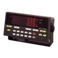
(2) Type: L2 (manual calibration)
EXA
ZR402G
~
<2> ZR402G Converter
Check valve
or Stop valve
<3> ZA8F Flow Setting Unit
<1> ZR22G Detector
100 to
240 V AC
Air Set
Instrument air
Calibration gas
Reference
gas
Flowmeter
Needle
valve
Zero gas cylinder
*2
Span gas
Check valve
Dust filter
Contact input
Analog output, contact output
(Digital output HART)
Signal
*1
(6-core shield cable)
Heater (2-core)
Regulator
No. Check Sketch of shadeName
1
2
3
General-purpose detector (with check valve or stop valve)
Detector with probe protector (same as above)
Detector with filter (same as above)
Note : Detector can be selected from among the following
F0302.ai
See Section 3.3 for details concerning detectors.
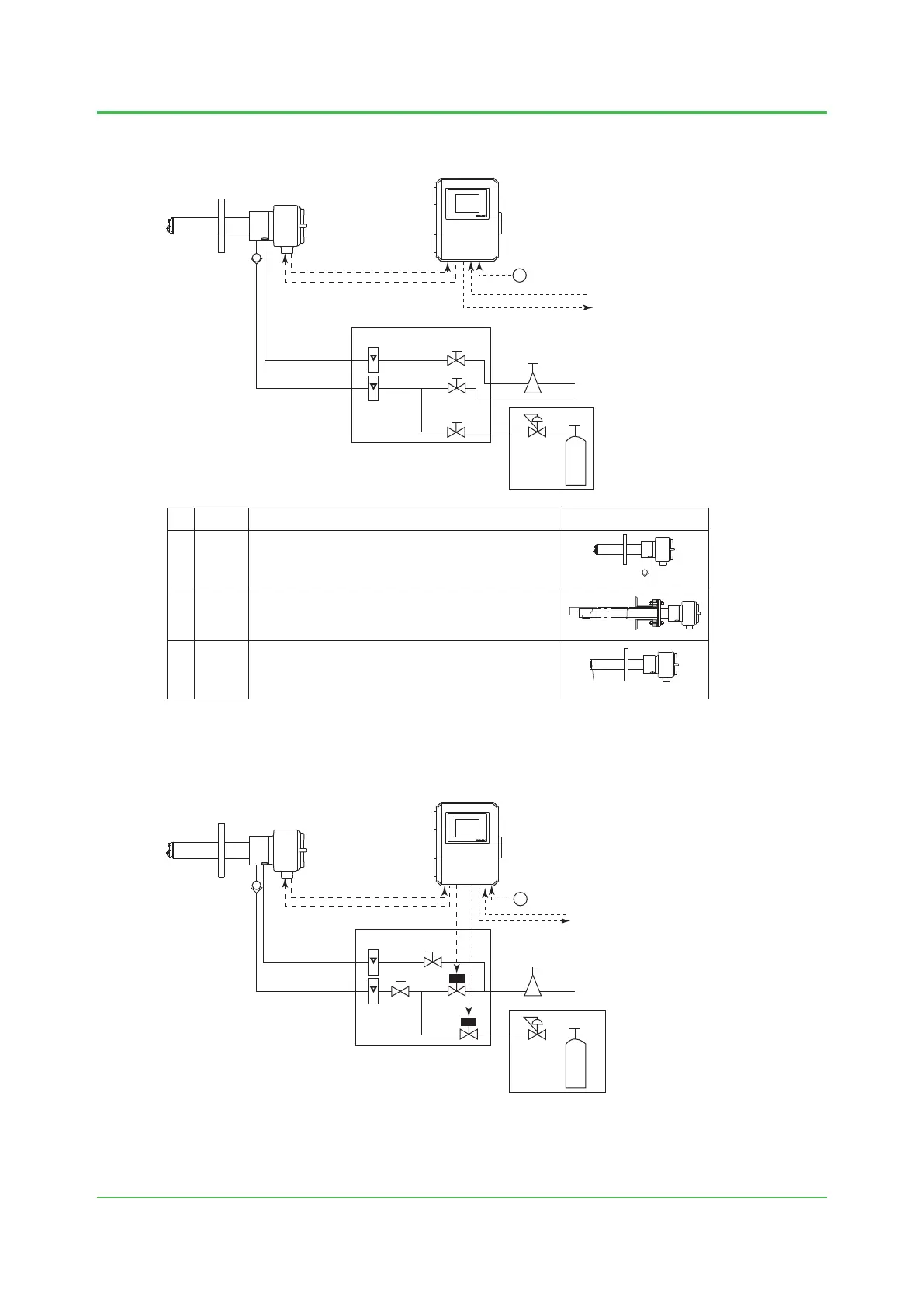
(3) Type: L3 (automatic calibration)
F0303.ai
EXA
ZR402G
~
<1> ZR22G Detector <2> ZR402G Converter
Signal
*1
(6-core shield cable)
Heater (2-core)
Reference gas
Calibration gas
Flowmeter
Needle
valve
Zero gas cylinder
*2
100 to 240 V AC
Check valve
<3> ZR40H Automatic
Calibration Unit
Contact input
Analog output, contact output
Digital output (HART)
lnstrument air
Regulator
Air Set
*1: Shield cable; Use shielded signal cables, and connect the shield to the FG terminal of the converter.
*2: When a zirconia oxygen analyzer is used, 100% N
2
gas cannot be used as the zero gas. Use approximately 1% of O
2
gas
(N
2
-based).
 Loading...