<2. Installation Guide>
2-2
TI 11M12A01-01EAll Right Reserved Copyright © 2004, Yokogawa Electric Corporation
Mar. 14, 2017-00
Installation Site of the Converter (in case of ZR402G)
1. Allows the operator to easily read the display and operate the keys.
2. Easy access for inspection and maintenance.
3. Ambient temperature does not exceed 55°C, and temperature variations are minimal.
4. Humidity is moderate (40 to 75% RH) and no corrosive gases are present.
5. Minimum vibration.
6. Near to the detector.
7. Not exposed to direct sun light.
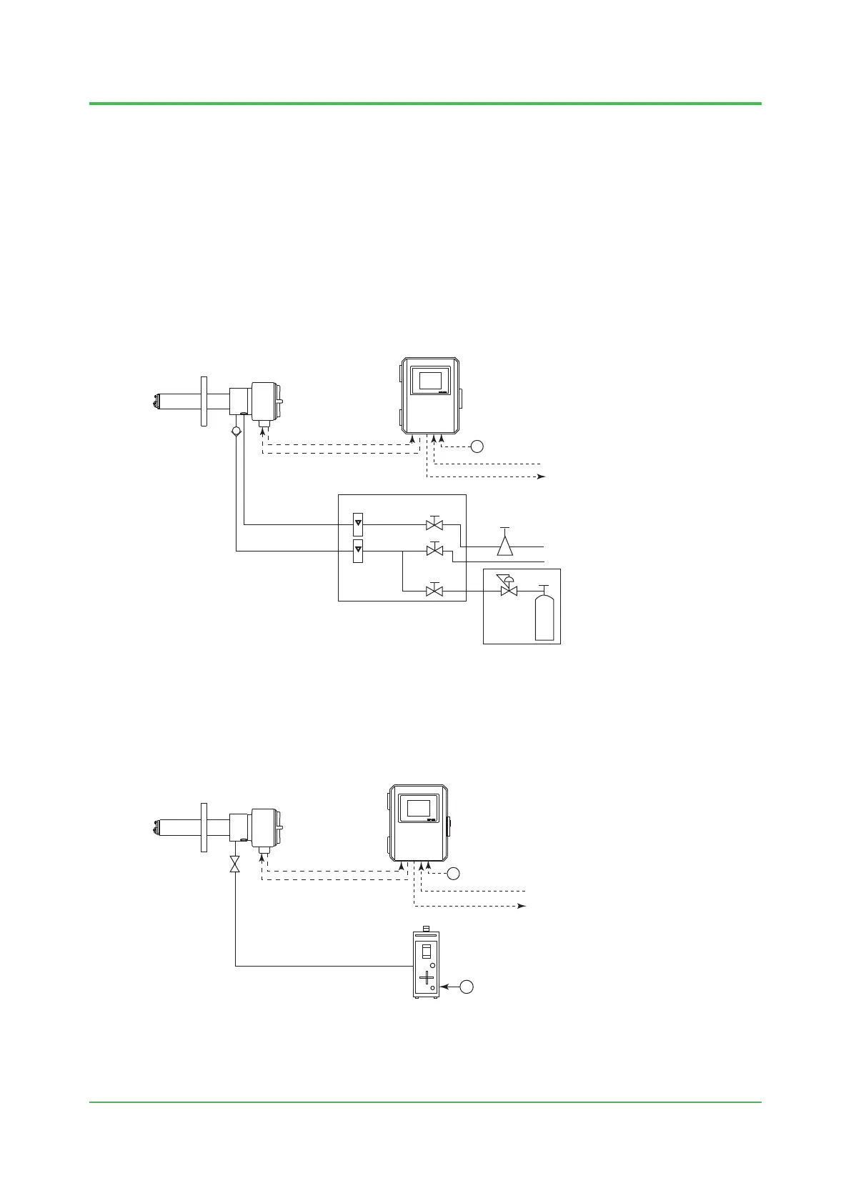
Instrument air is used as the reference gas
EXA
ZR402G
~
ZR402G Converter
Check valve
or Stop valve
ZA8F Flow Setting Unit
ZR22G Detector
100 to
240 V AC
Air Set
Instrument air
Calibration gas
Reference gas
Flowmeter
Needle
valve
Zero gas cylinder
Span gas
Contact input
Analog output, contact output
(Digital output HART)
Signal
(6-core shield cable)
Heater (2-core)
F0202.ai
1) Install the stop valve or check valve securely so that the gas does not leak.
2) Use the ZA8F flow setting unit and zero gas cylinder.
3) Use a shielded cable for the signal line.
Regulator
Ambient air is used as the reference gas
EXA
ZR402G
F0203.ai
~
~
ZR22G Detector
1) Install the stop valve securely so that the gas does not leak.
2) Use the ZO21S standard gas unit.
3) Use a shielded cable for the signal line.
ZR402G Converter
Stop valve
Calibration gas
ZO21S Standard gas unit
100 to
240 V AC
Contact input
Analog output, contact output
(Digital output HART)
Signal
(6-core shield cable)
Heater (2-core)

 Loading...