IM 12B07D02-01E
Installation and wiring 3-7
3-5. Wiring the sensor system
3-5-1. Impedance measurement jumper settings
NOTE:
It is important to decide first which application and which settings are appropriate for the
installation. This decision is best made before the jumpers are installed, because the cables will
rest beside the jumpers in their installed positions.
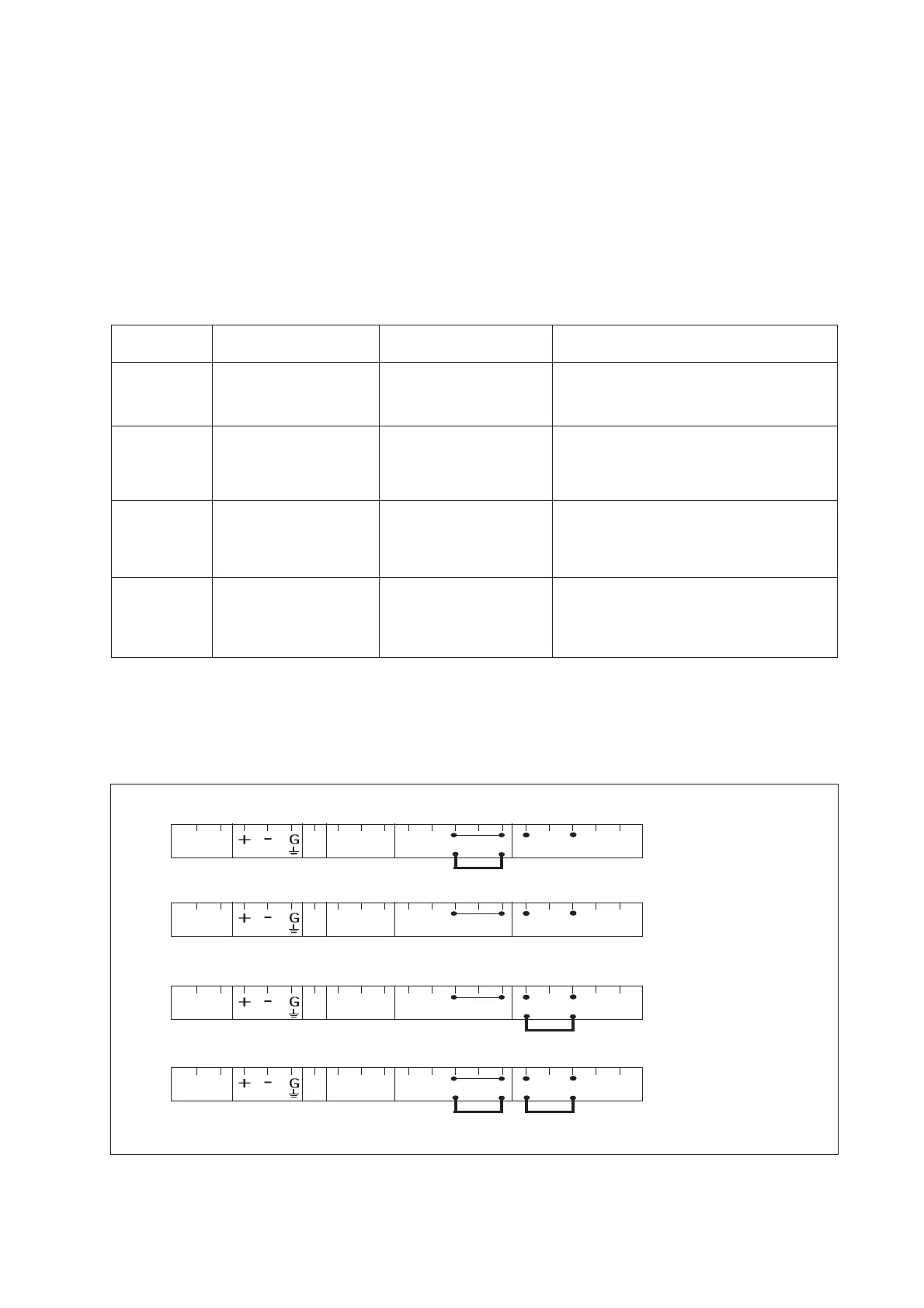
Table 3-1. Impedance measuring jumpers
Figure no. Jumper Settings Jumper Settings Application & Sensor Connections
Input #1 Input #2
1 High Impedance Low Impedance Normal pH sensors
Glass sensor on Input #1
Reference sensor on Input #2
2 High Impedance High Impedance Special electrodes using
2 glass sensors
(e.g. Pfaudler 18)
3 Low Impedance High Impedance ORP (pH compensated) and/or rH
metal sensor on Input #1
pH glass (as reference) on Input #2
4 Low Impedance Low Impedance ORP (Redox measurement)
metal sensor on Input #1
Normal reference on Input #2
For convenience insulated jumper links are provided. Ordinary wire links can also be used, and are just
as effective.
The following four jumper figure illustrations (figure 3-8) show the jumper positions related to the figure
numbers in the above table.
11 12 14 17 13 15 16
HIGH IMPLOW IMP
SUPPLY TEMP LE
INPUT 2
INPUT 1
11 12 14 17 13 15 16
HIGH IMPLOW IMP
SUPPLY TEMP LE INPUT 2 INPUT 1
11 12 14 17 13 15 16
HIGH IMPLOW IMP
SUPPLY TEMP LE
INPUT 2
INPUT 1
11 12 14 17 13 15 16
HIGH IMPLOW IMP
SUPPLY TEMP LE
INPUT 2 INPUT 1
1
2
3
4
Setting on shipment
Fig. 3-8. Jumper positions
 Loading...