IM 12B07D02-01E
Appendix 11-3
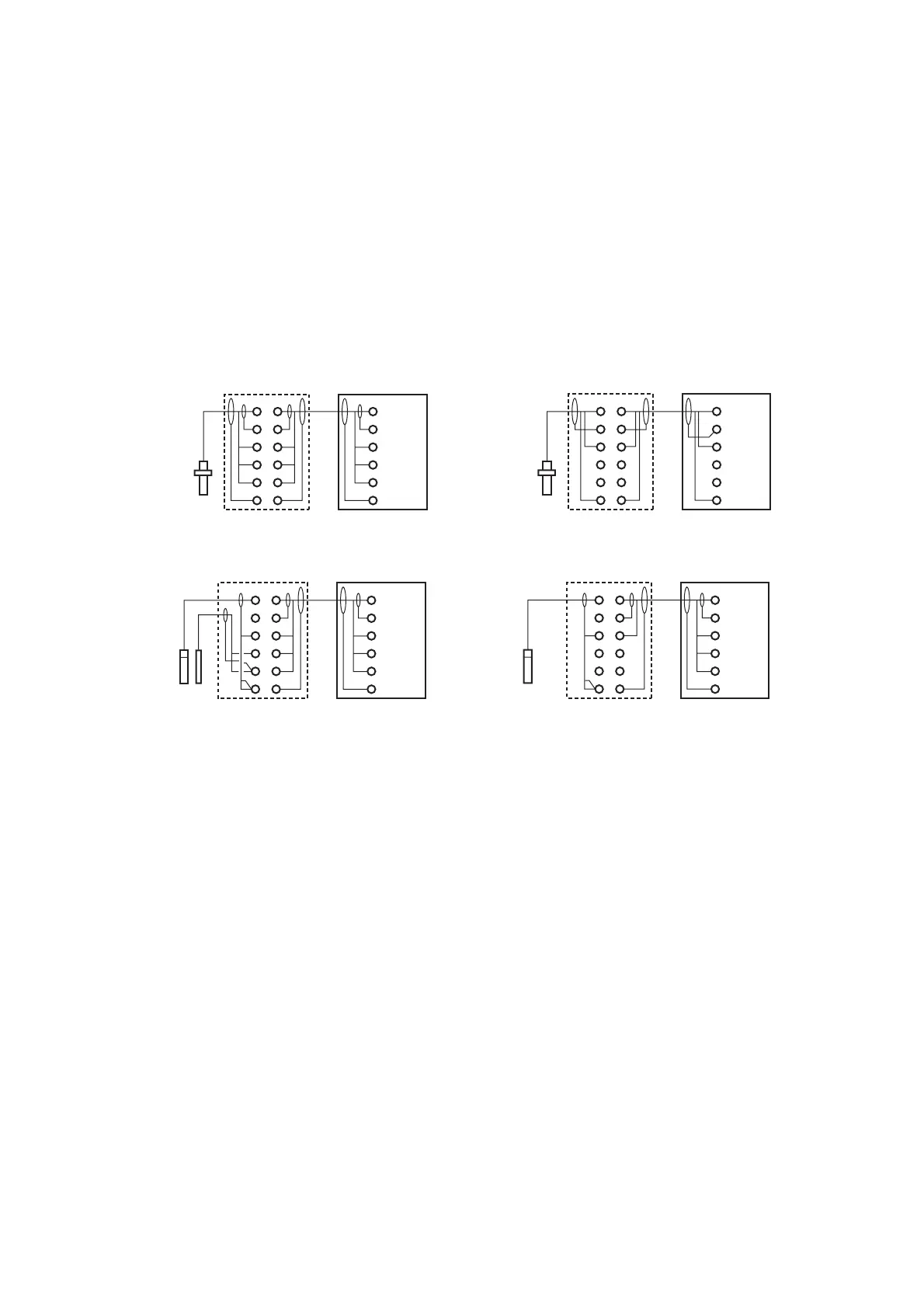
11-3-1. Connection cable
To connect the other sensor systems, follow the general pattern of the terminal connections as
listed below:
11 & 12 Temperature compensation resistor input
(Pt100, Pt1000, 3kPTC, 5.1kPTC, 8.55kNTC, 350PTC, 6.8kPTC, 10kPTC)
13 Input no. 2 (normally the reference element)
14 Liquid earth (solution ground) connection
15 Input no. 1 (normally the measuring element)
16 Screen (shield) for input no. 1
17 Screen (shield) for input no. 2
15
PH8EFP
PH8ERP
PH8EHP
*2
WTB10-PH1 *1
Terminal Box
PH202G, S
pH/ORP transmitter
16
13
12
11
141
15
16
13
12
11
14
15
SA405
HA405
HF405
DPA405
DPAS405
*2
WTB10-PH2 *3
Terminal Box
16
13
12
11
14
15
16
13
12
11
14
15
OR8EFG
OR8ERG
*2
16
13
12
11
14
15
16
13
12
11
14
15
HA485
DPA485
DPAS485
*2
16
13
12
11
14
15
16
13
In connecting to a gerneral purpose ORP sensor
In connecting to a general purpose pH sensor
12
11
14
In connecting to a special purpose pH sensor
In connecting to a special purpose ORP sensor
WTB10-PH1 *1
Terminal Box
WTB10-PH1 *1
Terminal Box
PH202G, S
pH/ORP transmitter
PH202G, S
pH/ORP transmitter
PH202G, S
pH/ORP transmitter
*1 : Terminal Box is used only when pH/ORP transmitter is installed far from the cable length of pH/ORP sensor.
*2 : The cable is specified by an option code of the terminal box.
*3 : Use the box in combining PH202 with SA405.
F3.6.1E.eps
Figure 11-1 Wiring of a sensor
 Loading...