<2. Wiring and Installation>
12
IM 12A01A02-12E 9th Edition : Mar. 23, 2018-00
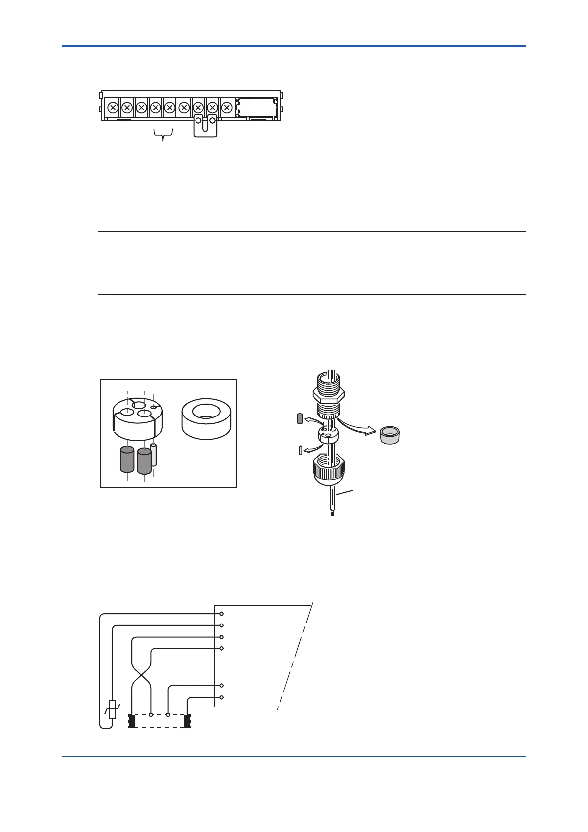
For pH Compensated ORP sensors, the jumper is placed as illustrated:
16
15191713181412
11
PH
Input 1
Input 2
Metal sensor on Input 1.
pH glass (as reference) on Input 2.
NOTE
ThespecialgrommetisintendedtobeusedtosealthemultiplecablesfromtheYokogawaow
ttingssuchasFF20.
The designated cables are WU20 sensor cables, which are approximately 5 mm (0.2”) in
diameter, and K1500FV liquid earth cables, which are approximately 2.5 mm (0.1”) in diameter.
For sensor systems using a single cable, like the FU20/FU24 and the PR10, PD20, PF20 and
PS20, the standard gland will accommodate the cable adequately. Single cables between
approximately 6 mm and 12 mm (0.24” and 0.47”) can be sealed properly with these glands and
the standard tule.
Remove
standard tule
Sensor
Grommet set
Figure 2.8 Grommet set use
2.3.3 SC Measurement
Contacting Conductivity, SC, sensors are connected to the module as follows:
11 +
-
V-
i-
Temp
V+
i+
12
13
14
15
16
FLXA202/FLXA21
 Loading...


