4-14
<Toc> <Ind>
TI 05C01E02-01E 1st Edition : Oct. 31, 2001-00
The following operating procedure describes an example of setting the “deviation high
and low limit” (setpoint: 7) for the alarm-1 type, and “5°C“ for the alarm 1 hysteresis.
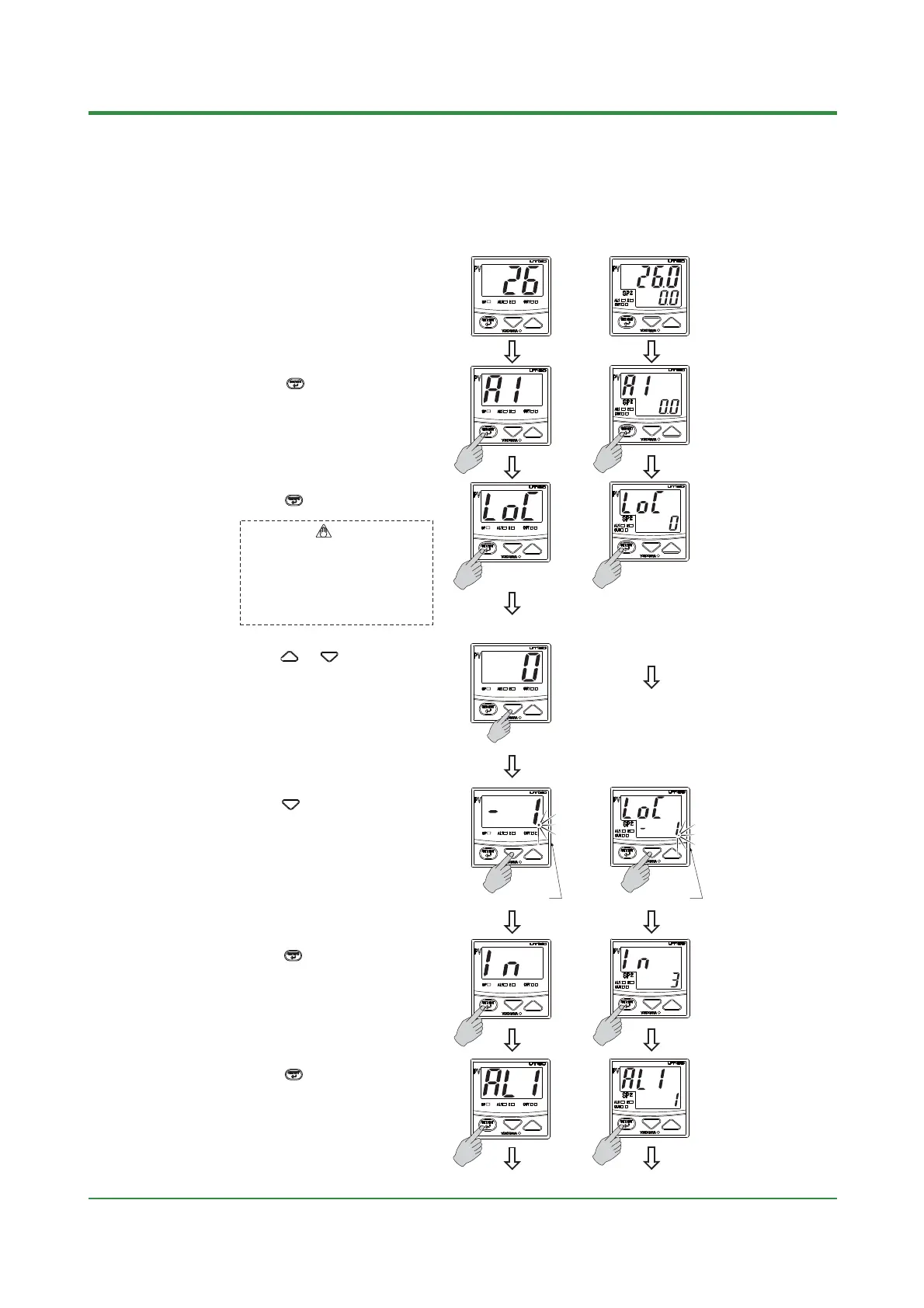
Step 1:
Bring the operating display into view.
UT130
Display example
UT150/UT152/UT155
Display example
Step 3:
Press the key several times to display
the parameter "CTL"(control mode).
Set "-1" to enter the setup parameter
setting display. But if "LOC" = 1 or 2 is
already set, the parameter value can not
be changed by setting "LOC" = -1 only. To
change the parameter value, set "LOC" = 0
at first (for disabling key lock), then set
"LOC" = -1 once again
NOTE
Step 5:
Press the key to display "-1".
Step 6:
Press the key once.
Flashes during change.
Flashes during change.
Step 2:
Press the key for 3 seconds or more
to display the parameter "A1".
The parameter "A1" appears only for the
controller with the "/AL" or" /HBA" option.
The parameter "CTL" appears for the
controller without the "/AL" or" /HBA" option,
and in this case, the alarm function is not
available.
Step 7:
Press the key several times to display
the parameter "AL1" (alarm 1 type).
The parameter "AL1" appears only for the
controller with the "/AL" or" /HBA" option.
To the next page
To the next page
Step 4
(for UT130 only)
:
Press the or key once to display
the setpoint.
<Operating Procedure>

 Loading...
