UTAdvanced UT35A/UT32A
List of Parameters
Operation Parameters
Operation Mode
Menu Symbol Name Display level Setting range Initial value User setting
MODE S.R STOP/RUN switch EASY
STOP: Stop mode
RUN: Run mode
Preset output (PO) is generated in STOP mode.
Default: Not displayed. STOP/RUN switch is assigned to contact input.
RUN
R.L REMOTE/LOCAL switch EASY
LCL: Local mode
REM: Remote mode
(Displayed only in cases where the communication is specified.)
LCL
AT Auto-tuning switch EASY
OFF: Disable
1 to 4: Perform auto-tuning. Tuning result is stored in the specified numbered
PID.
R: Tuning result is stored in the PID for reference deviation.
OFF
SPNO. SP number selection EASY 1 to 4 (Depends on the setup parameter SPGR. setting.) 1
PID PID number EASY
The PID group number being selected is displayed.
1 to 4, R: PID group for reference deviation
1
SELECT Parameter
Menu Symbol Name Display level Setting range Initial value User setting
CS CS10 SELECT parameter 10 EASY -
CS11 SELECT parameter 11 EASY -
CS12 SELECT parameter 12 EASY -
CS13 SELECT parameter 13 EASY -
CS14 SELECT parameter 14 EASY -
CS15 SELECT parameter 15 EASY -
CS16 SELECT parameter 16 EASY -
CS17 SELECT parameter 17 EASY -
CS18 SELECT parameter 18 EASY -
CS19 SELECT parameter 19 EASY -
SP and Alarm Setpoint Setting
Group 1
(SPNO.=1)
Group 2
(SPNO.=2)
Group 3
(SPNO.=3)
Group 4
(SPNO.=4)
Menu Symbol Name Display level Setting range Initial value User setting User setting User setting User setting
SP SP Target setpoint EASY 0.0 to 100.0% of PV input range (EU) (Setting range: SPL to SPH) SPL
SUB
Sub-target setpoint
(in Two-position two-level control)
EASY
Set the offset from SP.
-100.0 to 100.0% of PV input range span (EUS)
0.0 % of PV input range
span
PIDN PID number selection EASY 1 to 4 (Depends on the PIDG. setting.) Same as SP number.
A1 Alarm-1 setpoint EASY 0
A2 Alarm-2 setpoint EASY 0
A3 Alarm-3 setpoint EASY 0
A4 Alarm-4 setpoint EASY 0
SP-related Setting
Menu Symbol Name Display level Setting range Initial value User setting
SPS RT Remote input ratio STD
0.001 to 9.999
(Displayed only in cases where the communication is specified.)
1.000
RBS Remote input bias STD
-100.0 to 100.0% of PV input range span (EUS)
(Displayed only in cases where the communication is specified.)
0.0 % of PV input range
span
UPR SP ramp-up rate EASY OFF
DNR SP ramp-down rate EASY OFF
TMU SP ramp-rate time unit EASY
HOUR: Ramp-up rate or rampdown rate per hour
MIN: Ramp-up rate or ramp-down rate per minute
HOUR
SPT SP tracking selection STD OFF, ON ON
PVT PV tracking selection STD OFF, ON OFF
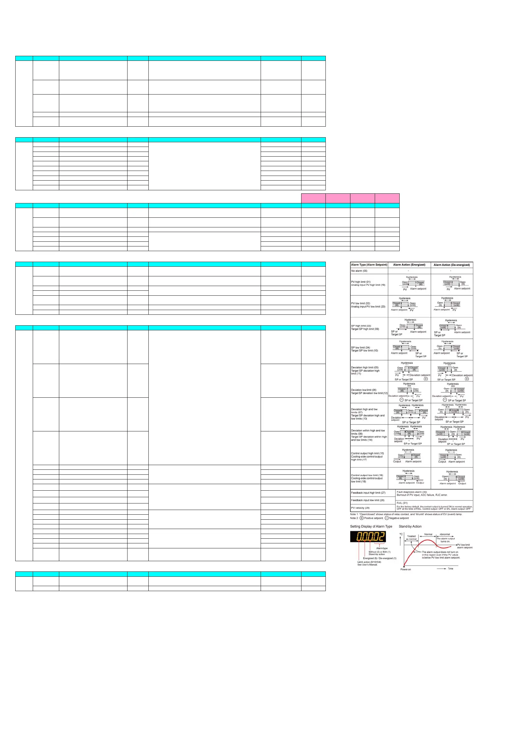
Alarm Function Setting
Menu Symbol Name Display level Setting range Initial value User setting
ALRM AL1 Alarm-1 type EASY
PV high limit (01)
Without Standby action (0)
Energized (0)
Latch action (0)
AL2 Alarm-2 type EASY
PV low limit (02)
Without Standby action (0)
Energized (0)
Latch action (0)
AL3 Alarm-3 type EASY
PV high limit (01)
Without Standby action (0)
Energized (0)
Latch action (0)
AL4 Alarm-4 type EASY
PV low limit (02)
Without Standby action (0)
Energized (0)
Latch action (0)
VT1 PV velocity alarm time setpoint 1 EASY 1.00
VT2 PV velocity alarm time setpoint 2 EASY 1.00
VT3 PV velocity alarm time setpoint 3 EASY 1.00
VT4 PV velocity alarm time setpoint 4 EASY 1.00
HY1 Alarm-1 hysteresis EASY 10
HY2 Alarm-2 hysteresis EASY 10
HY3 Alarm-3 hysteresis EASY 10
HY4 Alarm-4 hysteresis EASY 10
DYN1 Alarm-1 On-delay timer STD 0.00
DYN2 Alarm-2 On-delay timer STD 0.00
DYN3 Alarm-3 On-delay timer STD 0.00
DYN4 Alarm-4 On-delay timer STD 0.00
DYF1 Alarm-1 Off-delay timer PRO 0.00
DYF2 Alarm-2 Off-delay timer PRO 0.00
DYF3 Alarm-3 Off-delay timer PRO 0.00
DYF4 Alarm-4 Off-delay timer PRO 0.00
AMD Alarm mode STD
0: Always active
1: Not active in STOP mode
2: Not active in STOP or MAN mode
0
PV-related Setting
Menu Symbol Name Display level Setting range Initial value User setting
PVS BS PV input bias EASY -100.0 to 100.0% of PV input range span (EUS)
0.0 % of PV input range
span
FL PV input filter EASY OFF, 1 to 120 s OFF
0.00 to 99.59 (minute.second)
Set a 5-digit value in the following order.
[Alarm type: 2 digits (see below)] + [Without (0) or With (1) Stand-by action]
+ [Energized (0) or De-energized (1)] + [Latch action (0/1/2/3/4)]
Alarm type: 2 digits
00: Disable
01: PV high limit
02: PV low limit
03: SP high limit
04: SP low limit
05: Deviation high limit
06: Deviation low limit
07: Deviation high and low limits
08: Deviation within high and low limits
09: Target SP high limit
10: Target SP low limit
11: Target SP deviation high limit
12: Target SP deviation low limit
13: Target SP deviation high and low limits
14: Target SP deviation within high and low limits
15: OUT high limit
16: OUT low limit
17: Cooling-side OUT high limit
18: Cooling-side OUT low limit
19: Analog input PV high limit
20: Analog input PV low limit
27: Feedback input high limit
28: Feedback input low limit
29: PV velocity
30: Fault diagnosis
31: FAIL
0.01 to 99.59 (minute.second)
Set a display value of setpoint of hysteresis.
-19999 to 30000 (Set a value within the input range.)
Decimal point position depends on the input type.
When the decimal point position for the input type is set to "1", the initial
value of the hysteresis is "1.0".
0.00 to 99.59 (minute.second)
* Some parameters are not displayed according to the model and suffix codes or the setting of CNT parameter. For
details, refer to the User's Manual.
Setting range of a registered parameter.
See User's Manual.
Set a display value of setpoint of PV alarm, SP alarm, deviation alarm, output
alarm, or velocity alarm.
-19999 to 30000 (Set a value within the input range.)
Decimal point position depends on the input type.
OFF, 0.0 + 1 digit to 100.0% of PV input range span (EUS)
Page 11 / 18

 Loading...


