UTAdvanced UT35A/UT32A
Names and Functions of Display Parts
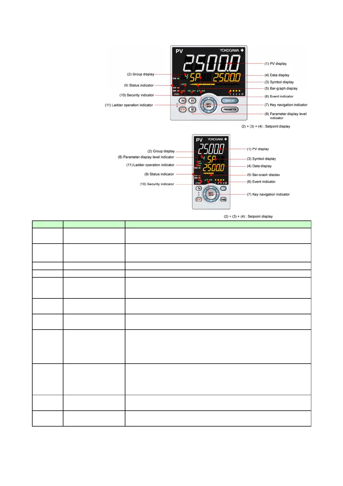
UT35A Dis
la
Parts
UT32A Dis
la
Parts
No. in figure
(1)
(2)
(3)
(4)
(5)
(6)
(7)
(8)
(9)
(10)
(11)
Lit while the ladder program operation is executed.
Ladder operation indicator
(green)
Displays PV. Displays an error code if an error occurs. Displays the scrolling guide in the
Menu Display and Parameter Setting Display when the guide display ON/OFF is set to ON.
Description
Displays a group number (1 to 4, or R) and terminal area (E1 to E4). 1 to 4 represent SP
numbers in the Operation Display. R and E1 to E4 are displayed in the Parameter Setting
Display.
Displays a parameter symbol.
Parameter display level
indicator
(green)
Status indicator
(green and red)
Security indicator (red)
Displays a parameter setpoint and menu symbol.
Displays control output value (OUT) and measured input value (PV).
The data to be displayed can be set by the parameter.
Initial value: deviation, in Heating/cooling control: heatingside control output
Lit when the alarms 1 to 4 occur.
Event displays other than alarms can be set by the parameter.
Lit or blinks when the Up/Down or Left/Right arrow key operation is possible.
Displays the setting conditions of the parameter display level function.
Parameter display level EASY PRO
Easy setting mode Lit Unlit
Standard setting mode Unlit Unlit
Professional setting mode Unlit Lit
Displays the operating conditions and control status.
Display Description
REM Lit when in remote mode (REM).
MAN Lit when in manual mode (MAN). Blinks during auto-tuning.
Lit if a password is set. The setup parameter settings are locked.
Data display (orange)
Bar-graph display
(orange and white)
Event indicator (orange)
Key navigation indicator
(green)
Name
PV display
(white or red)
Group display
(green)
Symbol display (orange)
Page 3 / 18

 Loading...


