Setup Parameters
Control Function Setting
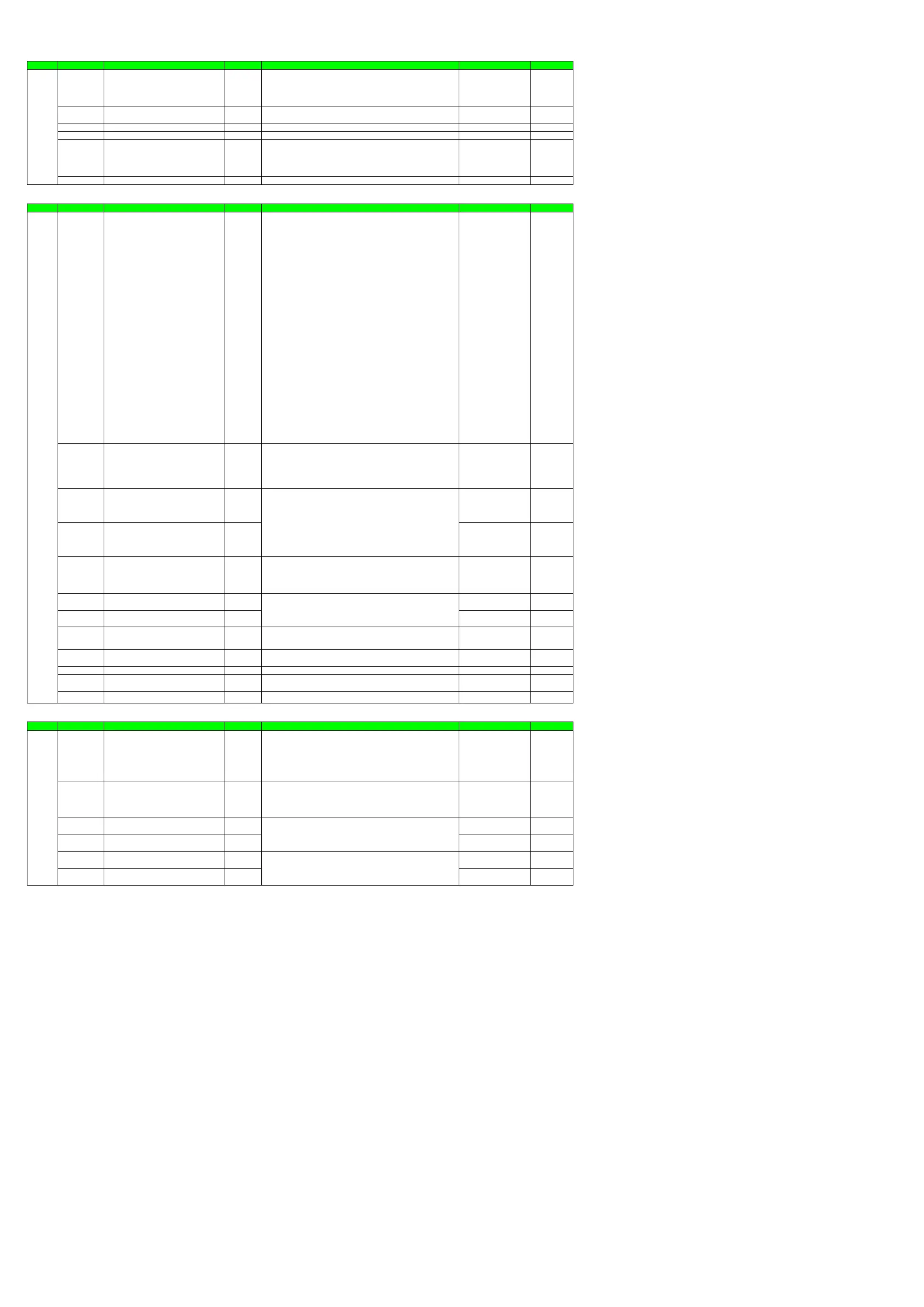
Menu Symbol Name Display level Setting range Initial value User setting
CTL CNT Control type EASY
PID: PID control
ONOF: ON/OFF control (1 point of hysteresis)
ONOF2: ON/OFF control (2 points of hysteresis)
2P2L: Two-position two-level control
H/C: Heating/cooling control
Standard type: PID
Heating/cooling type: H/C
ALG PID control mode PRO
0: Standard PID control mode
1: Fixed-point control mode
0
SPGR. Number of SP groups STD 1 to 4 4
ALNO. Number of alarms PRO 1 to 4 4
ZON Zone PID selection STD
0: SP group number selection 1
1: Zone PID selection (selection by PV)
2: Zone PID selection (selection by target SP)
3: SP group number selection 2
4: Zone PID selection (selection by SP)
0
PIDG. Number of PID groups STD 1 to 4 4
PV Input Setting
Menu Symbol Name Display level Setting range Initial value User setting
PV IN PV input type EASY
OFF: Disable
K1: -270.0 to 1370.0 (°C) / -450.0 to 2500.0 (°F)
K2: -270.0 to 1000.0 (°C) / -450.0 to 2300.0 (°F)
K3: -200.0 to 500.0 (°C) / -200.0 to 1000.0 (°F)
J: -200.0 to 1200.0 (°C) / -300.0 to 2300.0 (°F)
T1: -270.0 to 400.0 (°C) / -450.0 to 750.0 (°F)
T2: 0.0 to 400.0 (°C) / -200.0 to 750.0 (°F)
B: 0.0 to 1800.0 (°C) / 32 to 3300 (°F)
S: 0.0 to 1700.0 (°C) / 32 to 3100 (°F)
R: 0.0 to 1700.0 (°C) / 32 to 3100 (°F)
N: -200.0 to 1300.0 (°C) / -300.0 to 2400.0 (°F)
E: -270.0 to 1000.0 (°C) / -450.0 to 1800.0 (°F)
L: -200.0 to 900.0 (°C) / -300.0 to 1600.0 (°F)
U1: -200.0 to 400.0 (°C) / -300.0 to 750.0 (°F)
U2: 0.0 to 400.0 (°C) / -200.0 to 1000.0 (°F)
W: 0.0 to 2300.0 (°C) / 32 to 4200 (°F)
PL2: 0.0 to 1390.0 (°C) / 32.0 to 2500.0 (°F)
P2040: 0.0 to 1900.0 (°C) / 32 to 3400 (°F)
WRE: 0.0 to 2000.0 (°C) / 32 to 3600 (°F)
JPT1: -200.0 to 500.0 (°C) / -300.0 to 1000.0 (°F)
JPT2: -150.00 to 150.00 (°C) / -200.0 to 300.0 (°F)
PT1: -200.0 to 850.0 (°C) / -300.0 to 1560.0 (°F)
PT2: -200.0 to 500.0 (°C) / -300.0 to 1000.0 (°F)
PT3: -150.00 to 150.00 (°C) / -200.0 to 300.0 (°F)
0.4-2V: 0.400 to 2.000 V
1-5V: 1.000 to 5.000 V
4-20: 4.00 to 20.00 mA
0-2V: 0.000 to 2.000 V
0-10V: 0.00 to 10.00 V
0-20: 0.00 to 20.00 mA
-1020: -10.00 to 20.00 mV
0-100: 0.0 to 100.0 mV
Note: W: W-5% Re/W-26% Re (Hoskins Mfg. Co.), ASTM E988
WRE: W97Re3-W75Re25
OFF
UNIT PV input unit EASY
-: No unit
C: Degree Celsius
-: No unit
--: No unit
---: No unit
F: Degree Fahrenheit
C
RH Maximum value of PV input range EASY Depends on the input type
RL Minimum value of PV input range EASY Depends on the input type
SDP PV input scale decimal point position EASY
0: No decimal place
1: One decimal place
2: Two decimal places
3: Three decimal places
4: Four decimal places
Depends on the input type
SH Maximum value of PV input scale EASY Depends on the input type
SL Minimum value of PV input scale EASY Depends on the input type
BSL PV input burnout action STD
OFF: Disable
UP: Upscale
DOWN: Downscale
Depends on the input type
RJC PV input reference junction compensation PRO
OFF: RJC OFF
ON: RJC ON
ON
ERJC PV input external RJC setpoint PRO -10.0 to 60.0 (°C) 0.0
A.BS PV analog input bias STD -100.0 to 100.0% of PV input range span (EUS)
0.0 % of PV input range
span
A.FL PV analog input filter STD OFF, 1 to 120 s OFF
Input Range/SP Limiter Setting
Menu Symbol Name Display level Setting range Initial value User setting
MPV P.UNI Control PV input unit STD
-: No unit
C: Degree Celsius
-: No unit
--: No unit
---: No unit
F: Degree Fahrenheit
Same as PV input unit
P.DP Control PV input decimal point position STD
0: No decimal place
1: One decimal place
2: Two decimal places
3: Three decimal places
4: Four decimal places
Depends on the input type
P.RH Maximum value of control PV input range STD Depends on the input type
P.RL Minimum value of control PV input range STD Depends on the input type
SPH SP high limit STD 100.0 % of PV input range
SPL SP low limit STD 0.0 % of PV input range
-19999 to 30000, (SL<SH), | SH - SL | ≤ 30000
-19999 to 30000, (P.RL<P.RH), | P.RH - P.RL | ≤ 30000
0.0 to 100.0% of PV input range (EU), (SPL<SPH)
Depends on the input type.
- For temperature input -
Set the temperature range that is actually controlled. (RL<RH)
- For voltage / current input -
Set the range of a voltage / current signal that is applied.
The scale across which the voltage / current signal is actually controlled should
be set using the maximum value of input scale (SH) and minimum value of
input scale (SL).
(Input is always 0% when RL = RH.)
Page 13 / 18

 Loading...


