I
I
R
S
T
UU
U
I
N
I1
I2
I3
U3
U2
U1
Ur
Ut
Us
In
±
± ±
±
±
±
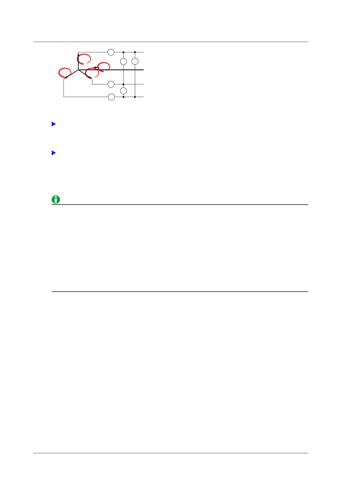
* In the measurement functions, rms, mn(mean), dc, rmn(r-mean), and ac are the delta computation modes.
A indicates the wiring unit.
For information about equations, see appendix 1 in the getting started guide, IM WT1801-03EN.
For information about the measurement period, see “Measurement Period.”
Delta Computation Modes (ΔMeasure Mode)
You can select the voltage or current mode to be displayed as delta computation values from the following:
rms, mean, dc, r−mean, ac
• We recommend that you set the measurement range and scaling (VT/CT ratio and coefficients) of the
elements that are undergoing delta computation as closely as possible. Using different measurement
ranges or scaling causes the measurement resolutions of the sampled data to be different. This results in
errors.
•
The numbers (1, 2, and 3) that are attached to delta computat
ion measurement function symbols have no
relation to the element numbers. The computation of all delta measurement functions, from ΔU1 to ΔPΣ,
varies depending on the wiring system and the delta computation type. For details, see appendix 1 in the
getting started guide, IM WT1801-03EN.
•
When only one element is installed in the WT1800, this feature
cannot be used, and its settings do not
appear.
• Delta computation cannot be performed on a single-phase, tw
o-wire (1P2W) wiring system.
Selecting an Element Whose Measurement Range You Want to
Specify (ELEMENT)
Select an element whose measurement range you want to specify. Press ELEMENT to switch in order between
the indicators of the installed elements. When independent input element configuration is off, the selected
elements will switch by wiring unit, according to the wiring system.
2 Fundamental Measurement Conditions

 Loading...


