IM 01C50B01-01E
6-1
6. MAINTENANCE
6. MAINTENANCE
6.1 General
Each component of this instrument is configured in
units to make maintenance easier.
This chapter contains disassembly and assembly
procedures associated with calibration, adjustment and
part replacement required for maintenance of the
affected instrument.
IMPORTANT
1. Maintenance of this instrument should be
performed in a service shop where the neces-
sary tools are provided.
2. Handling the CPU assembly
Some of the parts contained in the CPU
assembly are susceptible to static electricity
damage. Before performing maintenance, use
a ground wrist band or other antistatic mea
sures, and avoid touching the electronic
components and circuits with bare hands.
When removed from the instrument, keep the
CPU assembly in an antistatic bag.
6.2 Calibration
This instrument is fully factory-tested and is guaran-
teed for the intended accuracy, eliminating the need for
calibration. When calibration needs to be varified, the
following equipment and calibration procedure is
recommended.
6.2.1 Selection of Equipment for Calibra-
tion
Table 6.1 lists the equipment required for calibration.
The calibration equipment traceable to a verifying
agency standard should be used.
6.2.2 Calibration Procedure
To conduct calibration required to evaluate the uncer-
tainty while using the instrument, follow the steps
below:
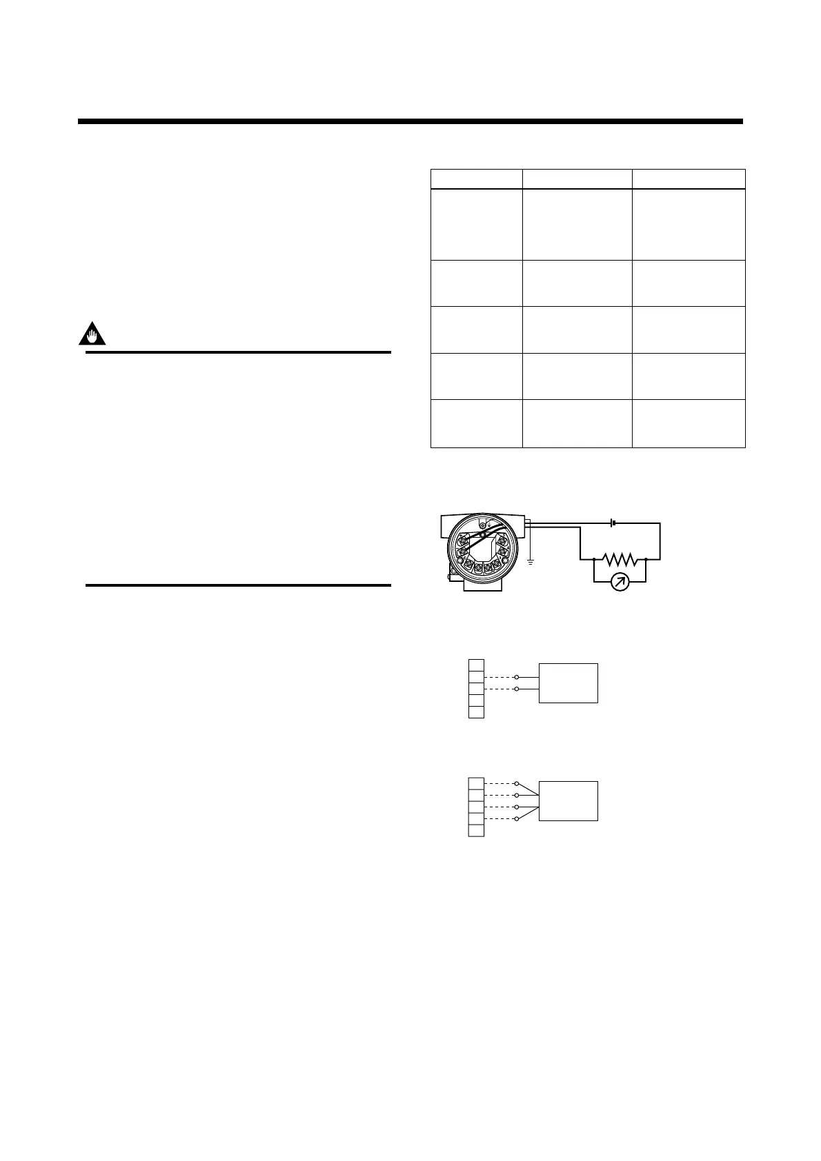
1. In accordance with the example wiring shown in
Figure 6.1, connect each equipment and initiate
warm up. Lay wiring on the input side according to
the sensor to be used.
Table 6.1 Calibration Equipment List
T0601.EPS
Power supply
2792 type standard
resistor
(250⍀ ±0.005%)
Voltmeter
Universal
calibrator
Variable resistor
SDBT, SDBS
type distributor
Model 1271 digital
multimeter
(accuracy: ±0.002%)
Model 9100 type
Load resistance
4 to 20mA DC
(Output voltage:
26.5±1.5V, drop by
internal 250⍀
resistance included)
For 4 to 20mA DC
For 4 to 20mA DC
signal
For calibration of
DC voltage and
thermocouple
For calibration of
thermometer resistor
(RTD) input
Name Recommended Remark
279301 type 6-dial
variable resistor
(accuracy: ±0.005%)
F0601.EPS
1
2
3
4
5
1
2
3
4
5
(A)
(B)
(B)
(A)
a. Wiring of power supply and output
b. Example of wiring for thermocouple
or DC voltage input
(when 1 input type is used)
+ Output signal
–
Load
resistance
DC voltage generator
Voltmeter
c. Example of wiring for thermometer
resistor 4-core type
(when 1 input type is used)
Variable resistor
(+)
(–)
Figure 6.1 Example of Wiring for Calibration Equipment
2. For DC voltage input
With a voltage generator, deliver input signals
corresponding to 0, 25, 75, or 100% of the input
span to the temperature transmitter. Measure the
resulting input signal with the voltmeter (digital
multimeter) and check the output value relative to
the input value.
 Loading...