IM 01C50B01-01E
6-2
6. MAINTENANCE
3. For thermocouple input
Since this instrument is equipped with a reference
junction compensating function, use a reference
junction compensating function in universal
calibrator in order to compensate for this function
upon calibration. According to the reference
milivolt table for thermocouple, obtain milivolt
corresponding to 0, 25, 50, 75, or 100% of the
span, and use that power as the input value, then
deliver it from the universal calibrator to the
temperature transmitter. Measure the resulting
output signal with the voltage meter (digital
multimeter) and check the output value relative to
the input value.
4. Thermometer resistor (RTD)
Using a thermometer resistor as input, calibration of
the temperature transmitter is carried out via a 4-
core wire connection.
As defined the reference resistor value table of the
thermometer resistor (RTD), obtain resistance
values corresponding to 0, 25, 50, 75 or 100% of
the span, and use the obtained resistance as the
input value, then deliver it to the temperature
transmitter by means of a variable resistor. Measure
the resulting output signal with the voltmeter
(digital multimeter) and check the output value
relative to the input value.
5. In Steps 2 through 4, if the output signal deviates
from the given range of accuracy when a given
input signal is delivered, adjust the output using the
handheld terminal. For details of how to adjust the
output, refer to the additional references, “BRAIN
Protocol” IM 01C50T03-01E or “HART Protocol”
IM 01C50T01-01E and the instruction manual for
each terminal.
6.3 Disassembly and Assembly
This section details the procedure for part replacement
or disassembly and assembly of each component
depending on the maintenance process.
Before starting disassembly and assembly work, turn
off the power, and use a tool suited to the associated
work.
Table 6.2 lists the tools required for disassembly and
assembly of the instrument.
Table 6.2 Tools for Disassembly and Assembly
T0602.EPS
Tool name Quantity Remark
Phillips screwdriver 1
Standard screwdriver 1
Hexagonal wrench 1
Crescent wrench 1
Torque wrench 1
Box wrench 1 For M10 screw
Box screwdriver 1
Forceps 1
CAUTION
Precautions for CENELEC and JIS Flame-
proof Type Transmitters
• For a withstand flameproof type transmitter, as
a rule, move the transmitter to a non-hazardous
location, then proceed with maintenance and
restore the instrument to the original condition.
• For a withstand CENELEC and JIS flameproof
type transmitter, turn the lock bolt (hexagon
socket bolt) clockwise with a wrench for hexa-
gon head, unlock and remove the cover. When
installing the cover, it is the must to turn the
lock bolt counterclockwise and lock the cover
(locked to a torque of 0.7 Nm).
• For a withstand flameproof type transmitter, in
no case should the user be allowed to modify
the transmitter. Therefore, no user is allowed to
add a built-in indicator, or use the transmitter
with the indicator removed. Contact us for any
modification.
F0602.EPS
Ter minal cover
Lock bolt
CPU assembly
Stud bolt
Mounting screw
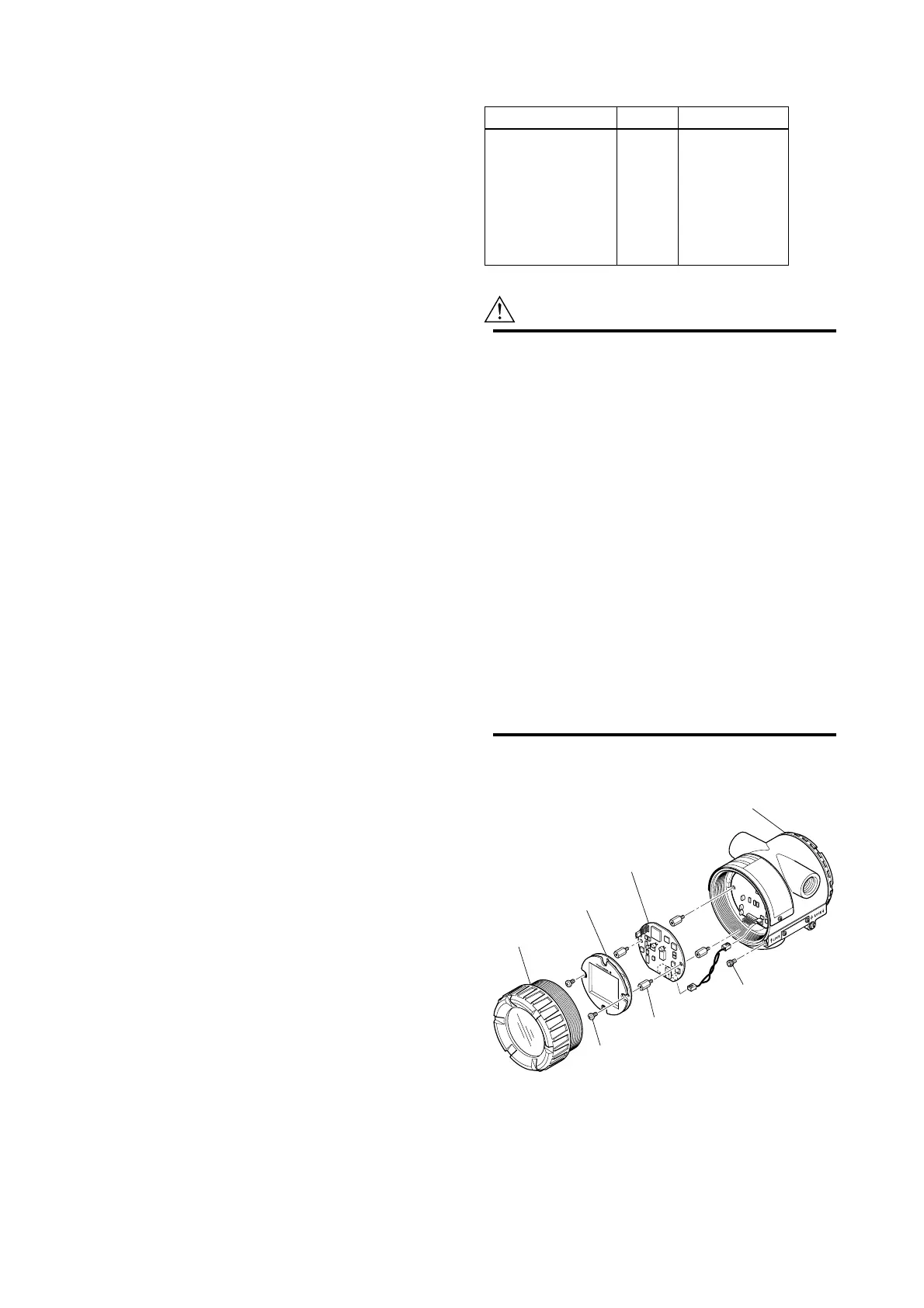
Amp. Cover
LCD board
(with indicator)
Figure 6.3 Mounting and Removal of Built-in Indicator
and CPU Assembly
 Loading...