Do you have a question about the York BUZ024 and is the answer not in the manual?
Covers essential steps for proper unit installation, adhering to codes and standards.
Details restrictions and guidelines for unit installation to ensure proper operation and safety.
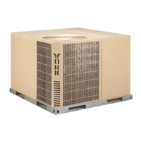
Provides guidance on selecting a suitable placement for the unit, considering airflow and environmental factors.
Explains the safe methods and precautions for moving and lifting the unit during installation.
Specifies required clearances around the unit for proper operation and servicing.
Presents detailed measurements of the unit's front dimensions and related features.
Details minimum clearance requirements for unit installation and servicing.
Illustrates the unit's front and bottom measurements and port locations.
Details the unit's back and bottom measurements and port locations.
Discusses requirements for designing and connecting ductwork for supply and return air.
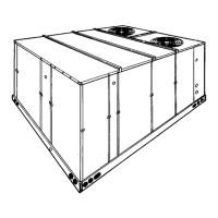
Information regarding the correct positioning of the unit on a roof curb.
Details the importance and maintenance of air filters for unit efficiency and longevity.
Instructions for installing the condensate trap and drain line, conforming to local codes.
Identifies locations for accessing serviceable components for maintenance and repair.
Guidance on thermostat placement, wiring, and power supply requirements for unit control.
Provides detailed electrical specifications including voltage, amperage, and fuse/breaker sizes.
Presents physical characteristics like capacity, EER, SEER, CFM, and dimensions.
Details the specific type of compressor used and its compatibility with R-410A refrigerant.
Explains how to identify and correct incorrect rotation for three-phase compressors.
Presents CFM data for various speed settings and static pressure conditions.
Table detailing airflow performance for side duct installations.
Table detailing airflow performance for bottom duct installations.
Table showing static resistance values for various components and airflow.
Specifies minimum required supply air CFM for electric heat operation.
Details specifications for the indoor blower motor, including HP, RPM, and frame size.
Provides multipliers to adjust electric heat capacity based on applied voltage.
Explains the function and bypass method for the compressor anti-short cycle timer.
Describes the sequence of events when the unit operates in cooling mode.
Describes the sequence of events when the unit operates in heating mode.
Details the unit's defrost cycle logic and initiation conditions.
Explains the function of safety switches protecting the refrigeration system and electric heat.
Details thermostat signals and board functions for single-phase units.
Details thermostat signals and board functions for three-phase units.
Covers routine tasks like filter changes and cleaning the outdoor coil.
Provides guidance on diagnosing and resolving common unit issues.
Overview of wiring diagrams for different unit configurations.
Specific wiring diagram for the 208/230-1-60 volt single-phase unit.
Specific wiring diagrams for the 230-3-60 and 460-3-60 volt three-phase units.