268723-BIM-C-0908
Johnson Controls Unitary Products 9
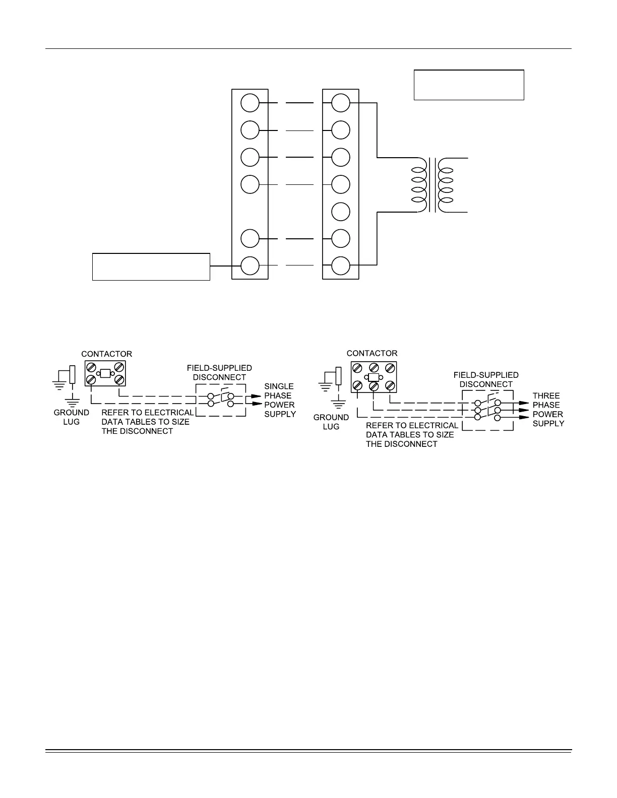
Figure 7: Typical Field Control Wiring Diagram
R
G
W
R
G
W
1
YY
W
2
O
C
O
C
** = Minimum wire size of 18 AWG
wire should be used for all field
installed 24 volt wire.
* = Only required on units with
supplemental electric heat.
PROGRAMMABLE
THERMOSTAT ONLY
THERMOSTAT
UNIT CONTROL BOARD
TERMINAL STRIP
24 VOLT
TRANSFORMER
*
*
*
NOTE: HEAT ANTICIPATOR
SHOULD BE SET AT 0.25
AMPS FOR ALL MODELS.
CAUTION: Label all wires prior to disconnection when servicing controls. Wiring errors cancause improper and
dangerous operation. Verify proper operation after servicing.