20
P5415484
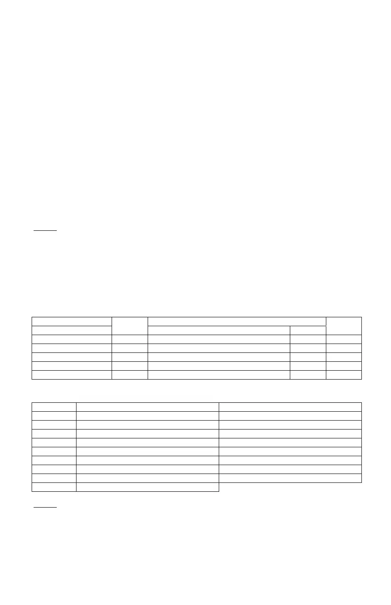
● Table B: Input and Output Number Display and Connectors
● Table C: Input and Output Settings and Display Codes
Input Number Display
Port
Factory Setting
Setting
Input/Output Indication Setting Item Indication
Input 1 CN3 1-2 Remote ON/OFF 1 (Level) 03
Input 2 CN3 2-3 Prohibiting Remote Control after Manual Stoppage 06
Output 1 CN7 1-2 Operation 01
Output 2 CN7 1-3 Alarm 02
Output 3 CN8 1-2 Thermo-ON for Heating 06
Code Indicated Input Output
00 Not set Not set
01 Room Thermostat (for Cooling) Operation
02 Room Thermostat (for Heating) Alarm
03 Remote ON/OFF 1 (Level) Cooling
04 Remote ON/OFF 2 (Operation) Thermo-ON for Cooling
05 Remote ON/OFF 2 (Stoppage) Heating
06 Forbidding Remote Control after Manual Stoppage Thermo-ON for Heating
07 Remote Cooling / Heating Change Not set
09 Setback Operation
NOTES:
* Change the optional setting after waiting at least 3 minutes elapsed time after start-up.
* Do not set the elevating grille for the total heat exchanger.
* Record the setting conditions for each input and output in the “Setting” column of the table.
NOTES:
1. Power ON, wait 3 minutes and then change the optional setting.
2. When changing the “CF” setting (change of louver swing angle), restore the power supply or allow the louver to
make one complete swing fully in the auto-swing mode to apply the optional setting.
3. The optional settings may be different according to the indoor and outdoor unit models.
Check to ensure that the unit has the optional setting.
4. Record the setting conditions for each optional setting in the “Setting” column of the table below.
5. The above optional functions marked with an “X” at the individual setting can change the condition only when “All
Rooms” is set.
(*1): Temperatures for Floor Exposed Type & Floor Concealed Types are not offset. Setting temperature are used as
they are.
(*2): The “02”, “03”, “04” settings may not be available depending on the type of indoor unit.
When connecting multiple indoor units, do separate settings.
(*3): If Duct type models, 00: Increasing fan speed 1 (standard), 01: Increasing fan speed 2 (high static pressure),
02: Standard (low static pressure).
(*4): Since it depends on the model, please refer to the Service Manual of each model.
(*5): If the set temperature is changed and kept within the set time at “F4”, the temperature is automatically changed
to “F5” and “F6”. (If the set temperature is out of range at “F5” and “F6”, it is applied within the upper and lower
limits for the set temperature.)
(*6): Applicable to the fan, cooling and dry operation modes.
(*7): Applicable to the heating operation mode.
(*8): If the operation on the wired controller is locked by this function (J4), Run/Stop state cannot be changed even in
the emergency. Make sure that this lock will NOT cause any inconvenience.
(*9): When the unit is restarted by the controller, the temperature automatically changes to the setting temperature of
“F5” or “F6”.
(*10): Available only for 4-Way Cassette Compact Type, 2-Way Cassette Type, 1-Way Cassette Type.
(*11): Available only for 4-Way Cassette Type, 4-Way Cassette Compact Type, 2-Way Cassette Type, 1-Way Cassette
Type, Ceiling Type.
(*12): Turning “P4” to “01” can select thermistor (sensor) that can show temperature setpoint.
(*13): Function “01” can show up sensor temperature selected by “P3”.