EasyManua.ls Logo

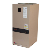
York F2FP060 User Manual

York F2FP060
20 pages
To Next Page IconTo Next Page
Page #1 background imageLoading...
Page #1 background image
INSTALLATION
MANUAL
CAUTION: READ ALL SAFETY GUIDES BEFORE YOU
START TO INSTALL YOUR UNIT.
SAVE THIS MANUAL
SINGLE PIECE AIR HANDLERS
HEAT PUMP MODELS
F2RP / F2FP018 THRU 060
F3RP / F3FP018 THRU 060
COOLING MODELS
F2RC / F2FC 024 THRU 036
035-14520-001 Rev. B (0803)
TABLE OF CONTENTS
GENERAL INFORMATION . . . . . . . . . . . . . . . . . . . . . . . 2
INSPECTION . . . . . . . . . . . . . . . . . . . . . . . . . . . . . . . . . . 2
REFERENCE . . . . . . . . . . . . . . . . . . . . . . . . . . . . . . . . . 2
LIMITATIONS . . . . . . . . . . . . . . . . . . . . . . . . . . . . . . . . . 2
LOCATION . . . . . . . . . . . . . . . . . . . . . . . . . . . . . . . . . . . 3
HORIZONTAL DRAIN PAN INSTALLATION /
CONVERSION . . . . . . . . . . . . . . . . . . . . . . . . . . . . . . . . 4
DIMENSIONS . . . . . . . . . . . . . . . . . . . . . . . . . . . . . . . . . .
DUCT CONNECTORS . . . . . . . . . . . . . . . . . . . . . . . . . . 5
AIR FILTERS . . . . . . . . . . . . . . . . . . . . . . . . . . . . . . . . . . 6
SUSPENSION KITS . . . . . . . . . . . . . . . . . . . . . . . . . . . . 6
COIL METERING DEVICES . . . . . . . . . . . . . . . . . . . . . . 6
REFRIGERANT LINE CONNECTION . . . . . . . . . . . . . . . 7
ELECTRIC HEATERS & OPERATING CONTROLS . . . 8
LOW VOLTAGE CONTROL CONNECTION . . . . . . . . . . 8
LINE POWER CONNECTIONS . . . . . . . . . . . . . . . . . . . . 8
BLOWER SPEED CONNECTIONS . . . . . . . . . . . . . . . . 8
DRAIN CONNECTIONS . . . . . . . . . . . . . . . . . . . . . . . . 19
MAINTENANCE . . . . . . . . . . . . . . . . . . . . . . . . . . . . . . . 19
COIL CLEANING . . . . . . . . . . . . . . . . . . . . . . . . . . . . . . 19
LUBRICATION . . . . . . . . . . . . . . . . . . . . . . . . . . . . . . . 19
CONDENSATE DRAINS . . . . . . . . . . . . . . . . . . . . . . . . 19
TROUBLESHOOTING GUIDE . . . . . . . . . . . . . . . . . . . 19

Questions and Answers:

York F2FP060 Specifications

General IconGeneral
Model NumberF2FP060
CategoryAir Handlers
Airflow2000 CFM
Voltage208-230V
Phase1
Motor TypePSC
Cabinet ConstructionGalvanized Steel
Cooling Capacity60, 000 BTU/h
InsulationFoil Faced

Summary

GENERAL INFORMATION

INSPECTION

Inspect unit for damage during transit and check all accessories before installation.

LIMITATIONS

Units must be wired and installed per national/local safety codes. Includes voltage and temperature limits.

LOCATION

COMBUSTIBLE MATERIAL CLEARANCES

Specific clearance requirements for combustible materials, especially when electric heat is used.

HORIZONTAL DRAIN PAN INSTALLATION/CONVERSION

DRAIN PAN POSITIONING AND PLUGGED DRAINS

Steps to position the horizontal drain pan, including removing plugs from used drain connections.

COIL BAFFLE AND BRACKET ADJUSTMENT

Instructions for moving coil support bracket and rotating baffle for left-hand horizontal applications.

COIL METERING DEVICES

ORIFICE AND TXV SIZING

Table listing installed orifice or TXV sizes for various indoor coil models.

TXV BULB INSTALLATION

Procedure for attaching the TXV temperature sensing bulb to the suction header line.

ORIFICE METERING DEVICE

ORIFICE SELECTION AND REPLACEMENT

Guidance on selecting the correct orifice based on system conditions and potential replacement.

ORIFICE INSTALLATION PROCEDURE

Step-by-step instructions for removing and installing a new orifice, including safety precautions.

REFRIGERANT LINE CONNECTION

CONNECTING REFRIGERANT LINES

Instructions for connecting refrigerant lines, ensuring proper routing and insulation of the suction line.

ELECTRIC HEATERS AND CONTROLS

ELECTRIC HEATER INSTALLATION AND JUMPER PLUG

Procedure for installing electric heaters and setting the jumper plug for cooling-only or heating operation.

LOW VOLTAGE CONTROL WIRING

Details on exiting low voltage wiring, using bushings, and connecting to control board terminals.

ELECTRICAL WIRING DIAGRAMS

ELECTRICAL DATA - 1Ø 208/230-1-60 HEATERS

ELECTRICAL DATA - SINGLE SOURCE 1Ø 208/230V

ELECTRICAL DATA - MULTI-SOURCE 1Ø 208/230V

ELECTRICAL DATA - SINGLE-PHASE 50 HZ

ELECTRICAL DATA - MULTI-SOURCE 1Ø 50 HZ

WIRING DIAGRAMS

DRAIN CONNECTIONS AND MAINTENANCE

TROUBLESHOOTING GUIDE

COMMON ISSUE DIAGNOSIS

Guide to diagnosing and resolving common problems like blower running continuously or no heat.

Related product manuals