FORM 160.54-M1(503)
73
YORK INTERNATIONAL
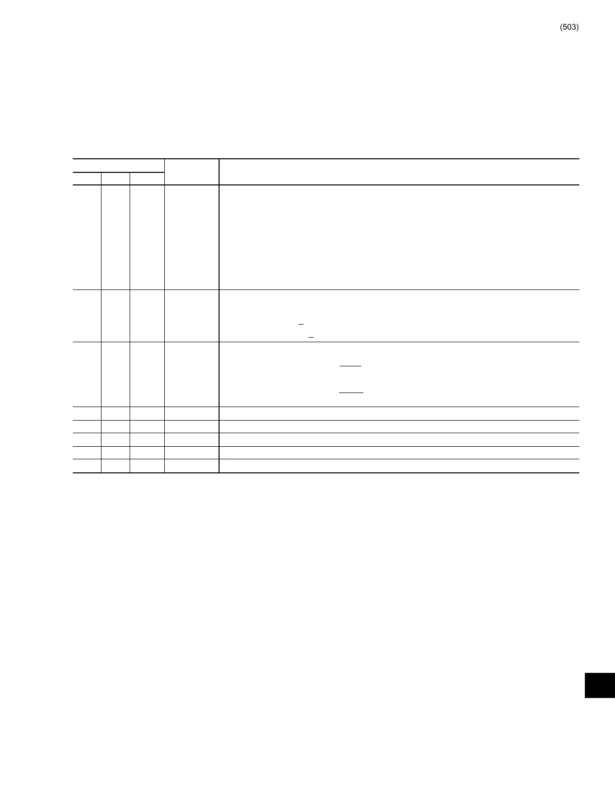
BINARY
DECIMAL OUTPUT
J6-1 J6-2 J6-3
0 0 0 0 Starter Model/Voltmeter/Ammeter full scale, max FLA:
0.41 to 0.77VDC - 7L, 600VAC, max FLA 281, full scale 787A
0.78 to 1.22VDC – 14L, 300VAC, max FLA 551, full scale 1574A
1.23 to 1.76VDC – 14L, 600VAC, max FLA 551, full scale 1574A
1.77 to 2.39VDC – 26L, 300VAC, max FLA 916, full scale 2938A
2.40 to 3.08VDC – 26L, 600VAC, max FLA 916, full scale 2938A
3.09 to 3.87VDC – 33L, 300VAC, max FLA 1134, full scale 3672A
3.88 to 5.00VDC – 33L, 600VAC, max FLA 1134, full scale 3672A
0 0 1 1 Current Limit commands
3.46 to 5.00VDC - <98% FLA
1.21 to 3.45VDC - >
100% FLA
0.0 to 1.20VDC - >
104% FLA
0 1 0 2 Phase “C” AC Power Line voltage as follows:
300VAC scale = VDC(out) = VAC
67.9
600VAC scale = VDC(out) = VAC
135.8
0 1 1 3 Phase “B” AC Power Line voltage. Same as Phase “C” above.
1 0 0 4 Phase “A” AC Power Line voltage Same as Phase “C” above.
1 0 1 5 Phase “A” Compressor Motor Current. 0 to +5VDC spanning range in address 0 above.
1 1 0 6 Phase “B” Compressor Motor Current. 0 to +5VDC spanning range in address 0 above.
1 1 1 7 Phase “C” Compressor Motor Current. 0 to +5VDC spanning range in address 0 above.
Power Line Voltages. Channels 5 through 7 are analog
volt ag es representing Phase A, B and C Compressor
Mo tor Current. The addresses are +12VDC for logic
high (1). <1VDC for logic low (0).
The Logic Board MUX address inputs, along with the
respective outputs are as follows:
11
 Loading...


