FORM 160.54-M1(503)
85
YORK INTERNATIONAL
The Proximity Position output of the Probe is mea sured
at the Microboard at J8-15 and is calculated as follows:
V = D - 8.14
20.86
D = 20.86 X V + 8.14
Where: V = VDC
D = distance in Mils
The High Speed Drain Temperature output of Probe
025-30961-000 is measured at the Microboard at J8-1
and is calculated as follows:
V = T - 18.75
62.5
T = 62.5 X V + 18.75
Where: V = VDC
T = Temp in Deg F
The chiller could be equipped with one of several dif fer ent
Probes. The Probe differences vary with the vintage. The
differences involve pri ma ri ly the power supply re quire -
ments and whether or not the Probe senses the High Speed
Drain Line Oil Temperature as detailed in the table below.
To de ter mine which Probe is present, examine the part
num ber printed on the Probe body. For service re place ment,
order the same Probe part number as pres ent ly installed
or refer to Renewal Parts Manual 160.54-RP1. An ap pro -
pri ate replacement will be provided. Microboard Pro gram
Jump ers JP41 and JP42 must be positioned ap pro pri ate ly
to provide proper operation for the actual probe installed.
Refer to Table 1 Micro, Microboard Pro gram Jump ers.
IMPORTANT
! Flash Memory Card version
C.MLM.01.03 or later (i.e. C.MLM.01.04, C.MLM.01.05,
etc.) must be used with Probe 025-35900-000 or 025-
xxxx-000. If the Flash Memory card does not meet this
requirement, a new Flash Memory Card (031-01797-
001) must be ordered at the same time as the Probe. If an
appropriate Flash Memory Card is not used, the chill er
will be pre vent ed from starting due to safety shut down
“Thrust Bearing – Oil Temperature Sensor” (com plete
explanation of this message in Op er a tion Manual
160.54-O1). This is due to the older Flash Memory
Card expecting to receive a High Speed Drain Line
Oil Tem per a ture value from the Probe and re place ment
Probes do not sense this temperature.
The Probe cannot accurately measure the gap distance
if its supply voltage, +12VDC or +24VDC, decreases
to <+9.5VDC or <19.0VDC respectively. To prevent an
invalid Proximity gap Safety shutdown due to a Utility
Power sag, the Microboard monitors the Probe’s +12VDC
or 24VDC power source at J9-12 on the Microboard. If
it decreases to <9.5VDC or <19.0VDC re spec tive ly, a
Cycling shutdown is per formed and “Proximity Probe
- Low Supply Voltage” is displayed. The chiller will
au to mat i cal ly restart when the voltage increases above
+9.5VDC for +12VDC ap pli ca tions and +19.7VDC for
+24VDC applications.
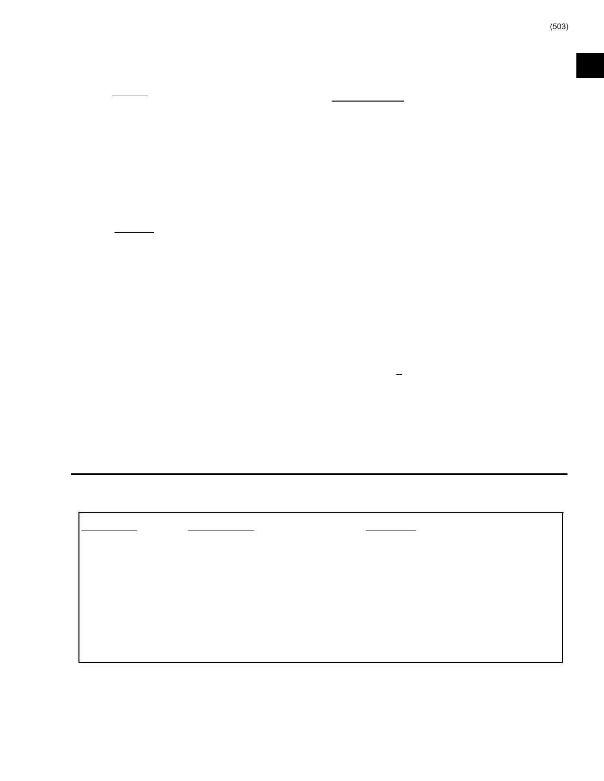
Part Number Supply Voltage Description
025-30961-000 +24VDC, +5VDC Production until April 2000. Senses Proximity. Also senses
High Speed Drain Line Oil Temperature unless equipped
with Flash memory card version C.MLM.01.03 or later.
025-35900-000 +24VDC, +5VDC Production after April 2000. Senses Proximity only. Does not
sense High Speed Drain Line Temperature.
025-xxxxx-000 +12/24VDC, +5VDC Future. Senses Proximity only. Does not sense High Speed
Drain Line Temperature.
13
 Loading...


