4 YORK INTERNATIONAL
TABLE OF CONTENTS
PAGE
Filter Drier Replacement.............................................................................. 42
Motor ............................................................................................................ 42
Determining Correct Refrigerant Charge Level .......................................... 42
Refrigerant Charging.................................................................................... 42
Refrigerant Leak Checking.......................................................................... 43
Pressure Connections .................................................................................. 43
Condenser Tubes.......................................................................................... 43
Condenser Water Side Tube Cleaning Procedure ....................................... 43
Chemical Cleaning Procedure .................................................................. 43
Mechanical Cleaning Procedure .............................................................. 44
Evaporator Tubes ......................................................................................... 44
Vibration Analysis ........................................................................................ 44
LIST OF ILLUSTRATIONS
FIGURE
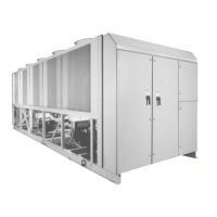
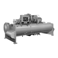
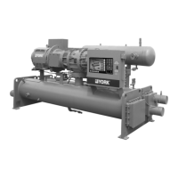
1 Model YS Style D Rotary Screw Liquid Chiller ................................. 5
2 Rigging ................................................................................................. 7
3 Standard Neoprene Vibration Isolator Pad Mounts ............................ 13
4 Overall Dimensions - English, S0 thru S3 Compressor ....................... 14
5 Overall Dimensions - English, S4 and S5 Compressor ....................... 15
6 Overall Dimensions - Std. Intl., S0 thru S3 Compressor..................... 16
7 Overall Dimensions - Std. Intl., S4 and S5 Compressor ..................... 17
8 Spring Isolators.................................................................................... 18
9 Schematic of a Typical Piping Arrangement for Cooling Units .......... 20
10 Typical Refrigerant Vent Piping from Relief Valves ........................... 21
11 Typical Refrigerant Vent Piping from Rupture Disk ........................... 22
12 YS Motor Connections (Electro-Mechanical Starter Application) ..... 25
13 Installation Check List and Request for Authorized Start-Up
Engineer
........................................................................................
26
14 Component Layout Drawing
...............................................................
28
15 Oil Piping Schematic
...........................................................................
30
16 Oil Separator Schematic
.....................................................................
32
17 Oil Filter Location
................................................................................
29
18 Oil Pressure Transducer Location
......................................................
31
19 Eductor Block
......................................................................................
31
20 Filter Driers and Oil Eductor
...............................................................
34
21 Oil Eductor Schematic
........................................................................
35
22 Refrigerant Schematic
........................................................................
36
23 Capacity Control Piping Schematic
.....................................................
38
24 4-Way Directional Valve Subplate
......................................................
37
25 Oil Heater and Sight Glass
..................................................................
41
26 Transducer Measurement Points
........................................................
45
PAGE
LIST OF TABLES
TABLE
1 Clearances........................................................................................... 6
2 Weights - English, R-22 and R-134a Units, 50 and 60 Hz .................. 8
3 Weights - SI, R-22 and R-134a Units, 50 and 60 Hz .......................... 10
4 Refrigerant Relief Characteristics ...................................................... 23
5 Variable Orifice Pressure Differential Setpoints................................. 34
6 York Oil Types .................................................................................... 39
7 Compressor Oil Limits ........................................................................ 39
8 Refrigerant Charge Level ................................................................... 42
9 Water Flow Velocities ......................................................................... 40
PAGE
 Loading...

