4. With the furnace in operation, paint the pipe joints and
valve gasket lines with a rich soap and water solution.
Bubbles indicate a gas leak. Take appropriate steps to stop
the leaks. If the leak persists, replace the component.
WARNING: DO NOT omit this test! NEVER use a flame to
check for gas leaks.
CHECKING GAS INPUT
1. Turn off all other gas appliances connected to gas meter.
2. With the furnace turned on, measure the time needed for
one revolution of the hand on the smallest dial on the
meter. A typical domestic gas meter usually has a 1/2 or 1
cubic foot test dial.
3. Using the number of seconds for each revolution and the
size of the test dial increment, find the cubic feet of gas
consumed per hour from Table 4.
NOTE: To find the Btuh input, multiply the number of cubic feet
of gas consumed per hour by the BTU content of the gas
in your particular locality. Contract your gas company for
this information, as it varies widely from city to city.
EXAMPLE:
It is found by measurement that it takes 26 seconds
for the hand to turn on the 1 cubic foot dial to make a revolution
with only a 120,000 Btuh furnace running. Using this informa-
tion, locate 26 seconds in the first column of Table 3.
Read across to the column headed "1 Cubic Foot" where you
will see that 138 cubic feet of gas per hour are consumed by
the furnace at that rate. Multiply 138 by 850 (the BTU rating of
the gas obtained from the local gas company). The result is
117,300 Btuh, which is close to the 120,000 Btuh rating of the
furnace.
If the actual input is not within ± 2% of the furnace rating, with
allowance being made for the permissible range of the regula-
tor setting (0.3 inches W.C.), replace the orifice spuds with
spuds of the proper size.
CAUTION: Be sure to relight any gas appliances that were
turned off at the start of this input check.
ADJUSTMENT OF MANIFOLD GAS PRESSURE
1. Turn gas off at main gas valve. Remove 1/8" plug in the main
gas valve body and install proper manometer tube adapter
fitting. Connect line from gas valve tap to manometer.
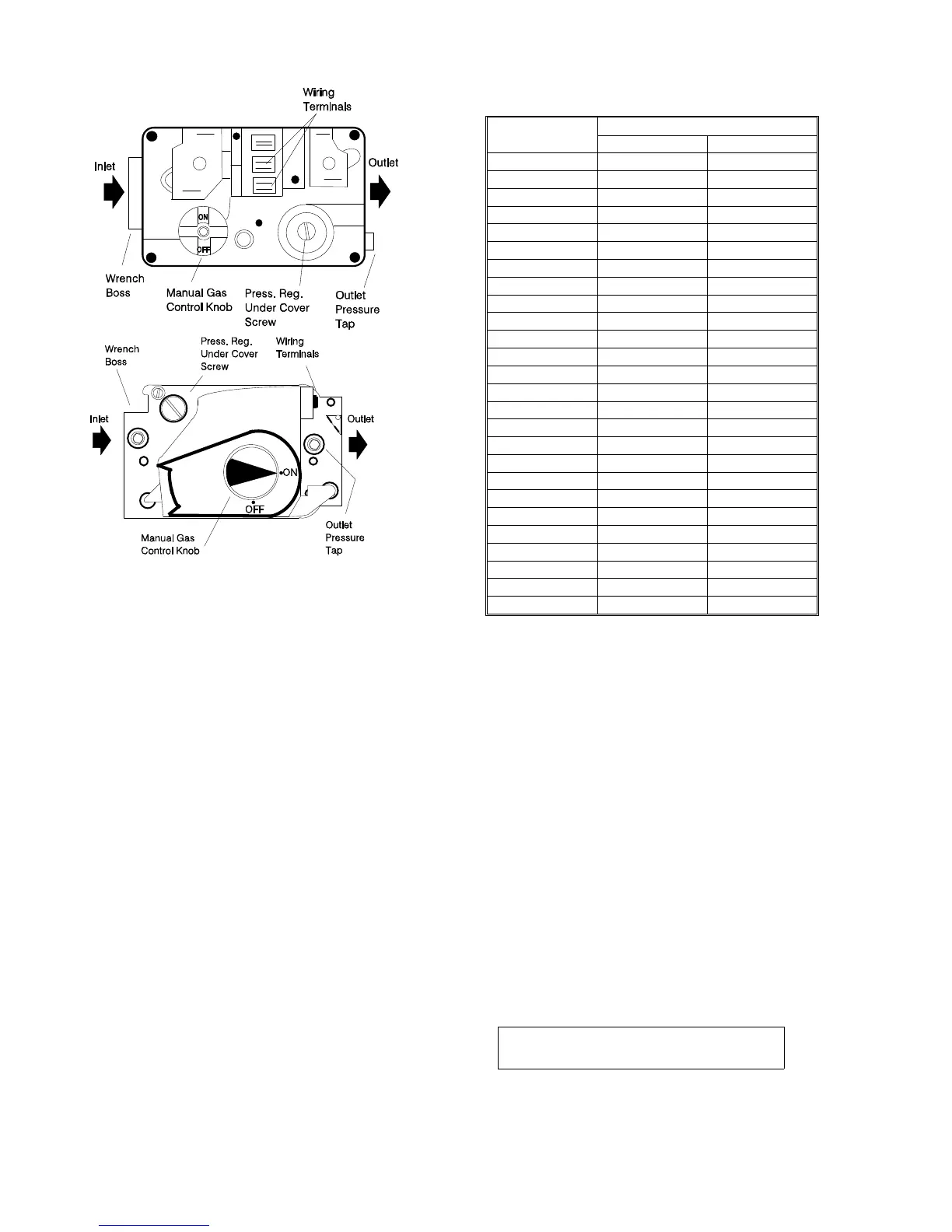
2. Refer to Figure 14 for location of pressure regulator adjust-
ment cap and screw on main gas valve.
NOTE: The screw-off cap for the pressure regulator must be
removed entirely to gain access to the adjustment screw.
WARNING: The cap must be replaced in order for the furnace
to operate properly.
3. Turn gas and electrical supplies ON. Start furnace and
observe manifold pressure on manifold.
4. Adjust manifold pressure by adjusting gas valve regulator
screw.
If gas valve regulator is turned in, or clockwise, manifold
pressure is increased. If screw is turned out, or counterwise,
manifold pressure will decrease.
WARNING: The manifold pressure must be checked with the
screw-off cap in place on the pressure regulator.
Natural Gas 3.5" W.C.
Propane (LP) 10.0" W.C.
FIGURE 14 - GAS VALVES
TOP - WHITE-RODGERS 36E97
BOTTOM - HONEYWELL VR8205
Seconds for
One Revolution
Size of Test Dial
1/2 cubic foot 1 cubic foot
10 180 360
12 150 300
14 129 257
16 113 225
18 100 200
20 90 180
22 82 164
24 75 150
26 69 138
28 64 129
30 60 120
32 56 113
34 53 106
36 50 100
38 47 95
40 45 90
42 43 86
44 41 82
46 39 78
48 37 75
50 36 72
52 35 69
54 34 67
56 32 64
58 31 62
60 30 60
TABLE 4 - GAS RATE (Cubic Feet Per Hour)
650.69-N3
12 Unitary Products Group
 Loading...