5322625-UIM-A-0417
6 Johnson Controls Unitary Products
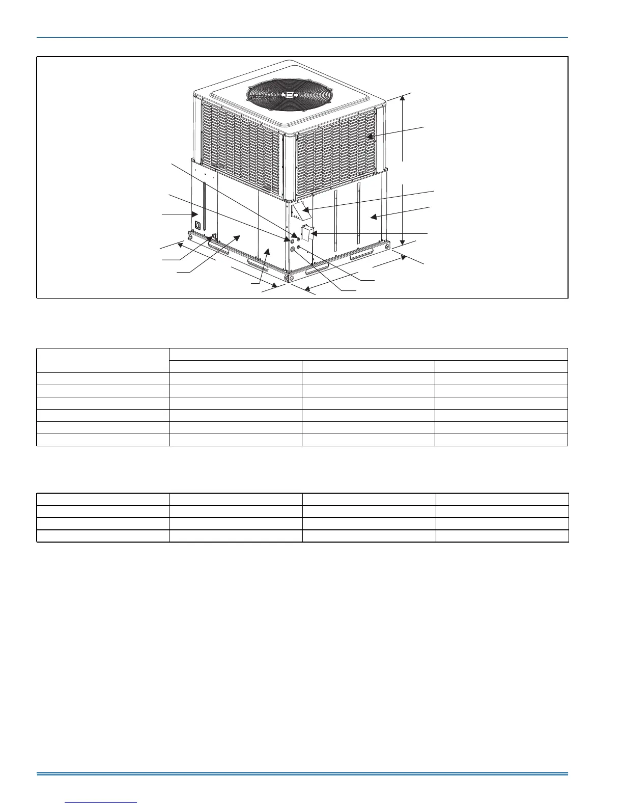
FIGURE 3: Unit Dimensions and Access Locations
HIGH VOLTAGE
CONNECTION 7/8”
HIGH VOLTAGE
CONNECTION 1-3/32”
COMPRESSOR
ACCESS PANEL
CONDENSATE
DRAIN
BLOWER
ACCESS
PANEL
CONTROL ACCESS
PANEL
LOW VOLTAGE CONNECTION
GAS SUPPLY
EXHAUST HOOD
COMBUSTION AIR INTAKE
HEAT EXCHANGER ACCESS PANEL
B
A
C
A0296-001
COIL GUARD
Table 3: Unit Dimensions and Access Locations
Model
Dimensions
ABC
PHG6A24 51-1/4 35-3/4 47
PHG6A30 51-1/4 35-3/4 49
PHG6B36 51-1/4 45-3/4 49
PHG6B42 51-1/4 45-3/4 49
PHG6B48 51-1/4 45-3/4 53
PHG6B60 51-1/4 45-3/4 55
Table 4: Unit Clearances
1
2
1. A 1" clearance must be provided between any combustible material and the supply air duct work.
2. The products of combustion must not be allowed to accumulate within a confined space and recirculate.
Direction Distance (in.) Direction Distance (in.)
Top
3
3. Units must be installed outdoors. Over hanging structure or shrubs should not obstruct outdoor air discharge outlet.
36 Power Entry (Right Side) 36
Side Opposite Ducts 36 Left Side 24
Duct Panel 0 Bottom
4
4. Units may be installed on combustible materials made from wood or class A, B or C roof covering materials only if factory base rails are left in place as shipped.
1