5322625-UIM-A-0417
8 Johnson Controls Unitary Products
SERVICE ACCESS
Access to all serviceable components is provided at the following loca-
tions:
• Coil guards
• Unit top panel
• Corner posts
• Blower access panel
• Control access panel
• Indoor coil access panel
• Compressor access panel
• Heat exchanger access panel
Refer to Figure 4 for location of these access locations and minimum
clearances in Table 4.
Refer to Figure 16 for the R-410A Quick Reference Guide.
THERMOSTAT
The room thermostat should be located on an inside wall approximately
60" above the floor where it will not be subject to drafts, sun exposure
or heat from electrical fixtures or appliances. Sealant should be used
behind thermostat to prevent air infiltration. The manufacturer's instruc-
tions are enclosed with the thermostat for general installation proce-
dure. Color coded insulated wires (minimum #18 AWG) should be used
to connect thermostat to unit. See Figure 6. The thermostat must be a
heat pump thermostat able to control fossil fuel backup heat. A 4H/2C
dual fuel heat pump thermostat is to be used.
Do not use power stealing thermostats.
POWER AND CONTROL WIRING
Field wiring to the unit must conform to provisions of the current N.E.C.
ANSI/NFPA No. 70 or C.E.C. and/or local ordinances. The unit must be
electrically grounded in accordance with local codes or, in their
absence, with the N.E.C./C.E.C. Voltage tolerances which must be
maintained at the compressor terminals during starting and running
conditions are indicated on the unit Rating Plate and Table 1.
The wiring entering the cabinet must be provided with mechanical strain
relief.
A fused disconnect switch should be field provided for the unit. If any of
the wire supplied with the unit must be replaced, replacement wire must
be of the type shown on the wiring diagram.
Electrical service must be sized properly to carry the load. Each unit
must be wired with a separate branch circuit fed directly from the main
distribution panel and properly fused.
Refer to Figure 7 for typical field wiring and to the appropriate unit wir-
ing diagram for control circuit and power wiring information. Unit comes
wired for 230 Volts power. If supply power is 208 Volts, wires connected
to control transformer 230V tap must be moved to the 208V tap.
CAUTION
This system uses R-410A Refrigerant which operates at higher pres-
sures than R-22. No other refrigerant may be used in this system.
Gage sets, hoses, refrigerant containers and recovery systems must
be designed to handle R-410A. If you are unsure, consult the equip-
ment manufacturer. Failure to use R-410A compatible servicing
equipment may result in property damage or injury.
WARNING
Wear safety glasses and gloves when handling refrigerants. Failure
to follow this warning can cause serious personal injury.
!
!
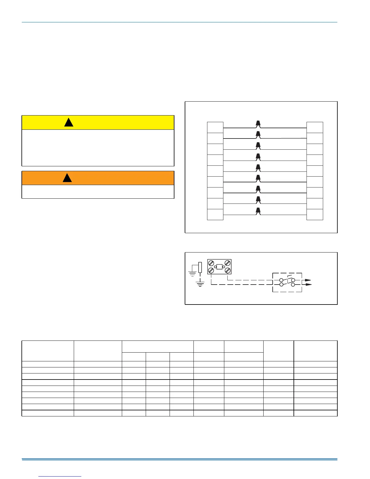
FIGURE 6: Typical Field Control Wiring Diagram For Dual Fuel
Models
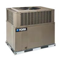
FIGURE 7: Typical Field Power Wiring Diagram
THERMOSTAT
NOTE:
Heat Anticipator should be set at 0.35 AMPS for all models.
CONTROL HARNESS
Minimum wire size of 18 AWG wire should be used for all eld
installed control wiring.
RED
ORANGE
YELLOW
BLUE
A0560-001
W1
Y1
O
R
C
O
R
C
W2
WHITE
G
G
Y2
HUM
HUM
W1
GREEN
GRAY
W2
WHITE/BLACK
Y2
YELLOW/BLACK
YorY1
CONTACTOR
FIELD SUPPLIED
DISCONNECT
GND
LUG
REFER TO ELECTRICAL
DATA TABLES TO SIZE
THE DISCONNECT
SINGLE
PHASE
POWER
SUPPLY
A0293-001
Table 5: Electrical Data
Model Voltage
Compressor
OD Fan
Motor
Supply
Blower Motor
MCA
1
(Amps)
Max Fuse
2
/
Breaker
3
Size
(Amps)
RLA LRA MCC FLA FLA
24050 208/230-1-60 11.7 58.3 18.2 0.7 2.6 17.9 25
24075 208/230-1-60 11.7 58.3 18.2 0.7 3.8 19.1 30
30050 208/230-1-60 13.1 73.0 20.4 0.8 2.6 19.8 30
30075 208/230-1-60 13.1 73.0 20.4 0.8 3.8 21.0 30
36065 208/230-1-60 15.3 83.0 23.8 1.7 3.8 24.6 35
36100 208/230-1-60 15.3 83.0 23.8 1.7 5.4 26.2 40
42065, 42100 208/230-1-60 17.9 96.0 28.0 1.7 5.4 29.5 45
48065, 48100, 48125 208/230-1-60 21.2 104.0 33.0 1.7 5.4 33.6 50
60065, 60100, 60125 208/230-1-60 28.8 152.9 45.0 1.7 7.0 44.7 70
NOTES:
1. Minimum Circuit Ampacity.
2. Maximum Over Current Protection per standard UL 1995.
3. Fuse or HACR circuit breaker size.