5402847-UIM-A-0917
Johnson Controls Unitary Products 13
In order to use this furnace in full communications (COMM) mode, it
MUST be installed with the matching touch-screen Communicating
Control (wall thermostat) and an outdoor air conditioner or heat pump
with a fully communicating control.
This furnace may be used with the Communicating Thermostat Control
and a non-communicating outdoor air conditioner by installing the AC
Communicating Control Board Kit to the outdoor unit. This system
allows full communication between the furnace and thermostat and lim-
ited communication to the outdoor unit. See Figure 18.
CONTROL WIRING USING COMMUNICATING
CONTROLS (NON-VARIABLE CAPACITY OUTDOOR
MODELS)
Use the wiring diagram above to connect the furnace control, Commu-
nicating Control (wall thermostat) and communicating outdoor unit. Be
sure that all of the “A” terminals are connected together, all of the “B”
terminals are connected together, all of the “GND” or “C” terminals are
connected together and all of the “R” terminals are connected together.
See Figure 18. When using a fully communicating system, the large
screw terminals (C, G, R, etc.) on the furnace control are not used. The
four small screw terminals in the terminal block on the end of the fur-
nace control should be used.
Float Switch Input
An optional switch may be connected to the FLT SWT terminals on the
control board. This feature is only functional when used with the Com-
munication Control. It is intended for use with a water overflow switch.
Auxiliary Switch Input
An optional switch may be connected to the AUX SWT terminals on the
control board. This feature is only functional when used with the Com-
munication Control. Refer to Communication Control Installation Man-
ual.
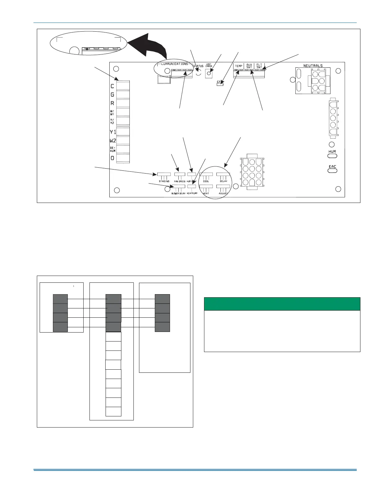
FIGURE 17: Furnace Control Board – Communications Connections
CONVENTIONAL
LOW VOLTAGE
TSTAT CONNECTIONS
COMMUNICATING
TSTAT CONNECTIONS
DIAGNOSTIC
LIGHT
LAST
ERROR
BUTTON
CFM
INDICATOR
FLOAT
SWITCH
CONNECTION
TEMP
SENSOR
CONNECTIONS
AUXILIARY
SWITCH
CONNECTIONS
HUMIDISTAT
SELECTION
HI HEAT
DELAY
BLOWER
OFF DELAY
CONTINUOUS
FAN SPEED
HEAT PUMP
SELECTION
AIRFLOW
SELECTION
A+ R C B- A+ R C B-
A+ R C B- A+ R C B-
COMMUNICATIONS
FIGURE 18: Two-stage Furnace with Communicating AC or HP
O
DHUM
Y1
Y/Y2
W2
R
G
C
Touch Screen
Communicating control
Furnace
Communicating control
Air Conditioner/Heat Pump
Communicating control
W/W1
IMPORTANT
Do not place more than one wire under any single communication
terminal screw (there are four communication terminal screws). If
more than one wire must be connected to a terminal screw, attach
only the terminal end of a one wire pigtail no longer than 6“, and
use a wire connector to connect the other end of the pigtail to the
other wires. Failure to do this will result in nuisance communication
error faults. See Figure 19.
 Loading...