5402847-UIM-A-0917
26 Johnson Controls Unitary Products
ADJUSTMENT OF TEMPERATURE RISE
The temperature rise, or temperature difference between the return air
and the heated supply air from the furnace, must be within the range
shown on the furnace rating plate and within the application limitations
as shown in Table 7.
After about 20 minutes of operation, determine the furnace temperature
rise. Take readings of both the return air and the heated air in the ducts,
about six feet (1.83 m) from the furnace where they will not be affected
by radiant heat. Increase the blower speed to decrease the temperature
rise; decrease the blower speed to increase the rise.
VARIABLE SPEED ECM MOTORS
The variable speed motor must be configured so the blower will provide
a sufficient airflow so that the furnace operates with in the temperature
rise range on the rating plate and within the application limitations
shown in Table 7 in these Instructions.
ADJUSTMENT OF FAN CONTROL SETTINGS
Heating Indoor Fan Off Delay
This furnace is equipped with a time-on/time-off heating fan control. The
fan on delay is fixed at 30 seconds. The fan off delay has 4 settings (60,
90, 120 and 180 seconds). The fan off delay is factory set to 120 sec-
onds. The fan-off setting must be long enough to adequately cool the
furnace, but not so long that cold air is blown into the heated space. The
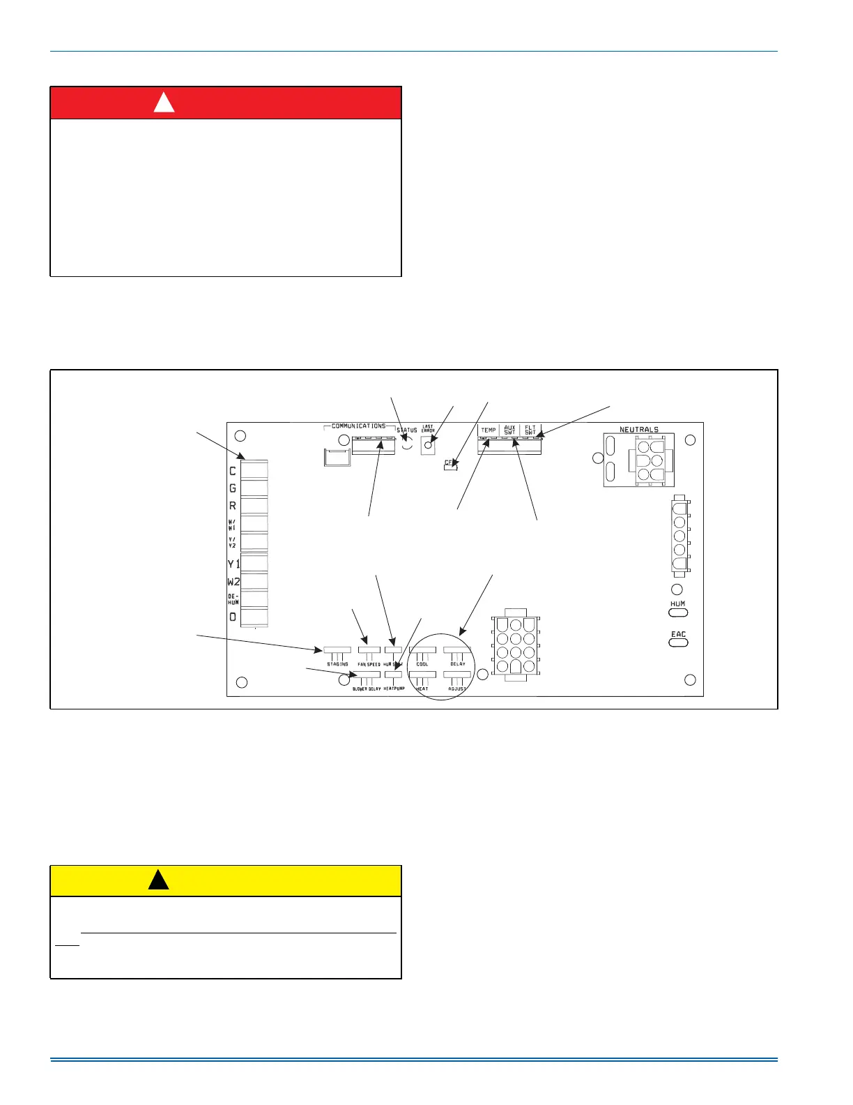
fan-off timing may be adjusted by positioning the jumper on two of the
four pins as shown in Figure 30.
SECTION VIII: SAFETY CONTROLS
CONTROL CIRCUIT FUSE
A 3-amp fuse is provided on the control circuit board to protect the 24-
volt transformer from overload caused by control circuit wiring errors.
This is an ATO 3, automotive type fuse and is located on the control
board.
BLOWER DOOR SAFETY SWITCH
This unit is equipped with an electrical interlock switch mounted in the
burner compartment. This switch interrupts all power at the unit when
the panel covering the blower compartment is removed.
Electrical supply to this unit is dependent upon the panel that covers the
blower compartment being in place and properly positioned.
ROLLOUT SWITCH CONTROLS
These controls are mounted on the burner assembly. If the temperature
in the area surrounding the burner exceeds its set point, the gas valve
is de-energized. The operation of this control indicates a malfunction in
the combustion air blower, heat exchanger or a blocked vent pipe con-
nection. Corrective action is required. These are manual reset controls
that must be reset before operation can continue.
PRESSURE SWITCHES
This furnace is supplied with pressure switches, which monitor the flow
through the combustion air/vent piping system. These switches de-
energizes the gas valve if any of the following conditions are present.
1. Blockage of vent piping or terminal.
2. Failure of combustion air blower motor.
DANGER
The temperature rise, or temperature difference between the return
air and the supply (heated) air from the furnace, must be within the
range shown on the furnace rating plate and within the application
limitations shown in Table 7 “ELECTRICAL AND PERFORMANCE
DATA”.
The supply air temperature cannot exceed the “Maximum Supply
Air Temperature” specified in these instructions and on the furnace
rating plate. Under NO circumstances can the furnace be allowed to
operate above the Maximum Supply Air Temperature. Operating the
furnace above the Maximum Supply Air Temperature will cause pre-
mature heat exchanger failure, high levels of Carbon Monoxide, a fire
hazard, personal injury, property damage, and/or death.
!
FIGURE 30: Furnace Control Board
CONVENTIONAL
LOW VOLTAGE
TSTAT CONNECTIONS
COMMUNICATING
TSTAT CONNECTIONS
DIAGNOSTIC
LIGHT
LAST
ERROR
BUTTON
CFM
INDICATOR
FLOAT
SWITCH
CONNECTION
TEMP
SENSOR
CONNECTIONS
AUXILIARY
SWITCH
CONNECTIONS
HUMIDISTAT
SELECTION
HI HEAT
DELAY
BLOWER
OFF DELAY
CONTINUOUS
FAN SPEED
HEAT PUMP
SELECTION
AIRFLOW
SELECTION
CAUTION
Main power to the unit must still be interrupted at the main power dis-
connect switch before any service or repair work is to be done to the
unit. Do not rely upon the interlock switch as a main power discon-
nect.
Blower and burner must never be operated without the blower panel
in place.
!
 Loading...