EasyManua.ls Logo

York YCAV0569 User Manual

York YCAV0569
278 pages
To Next Page IconTo Next Page
Page #1 background imageLoading...
Page #1 background image
R134a
MODELS YCAV0569-0969, 50 HZ
STYLE A
(492-879 KW)
E/V HIGH EFFICIENCY AND S/P STANDARD EFFICIENCY
LD10477
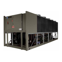
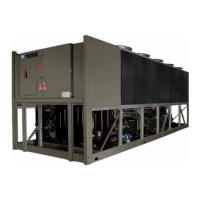
AIR-COOLED SCREW
LIQUID CHILLERS
INSTALLATION, OPERATION, MAINTENANCE Supesedes 201.21-NN2 (315) Form 201.21-NM2 (616)
Issue Date:
June 30, 2016
035-20993-000

Table of Contents

Questions and Answers:

York YCAV0569 Specifications

General IconGeneral
BrandYork
ModelYCAV0569
CategoryChiller
LanguageEnglish

Summary

GENERAL CHILLER INFORMATION & SAFETY

INTRODUCTION

Overview of YORK YCAV chillers, their design standards, and intended use for cooling water or glycol solutions.

WARRANTY

Details YORK International's warranty policy for equipment, covering defects in workmanship and materials for 18 months.

SAFETY

Outlines standards for YCAV chillers, compliance with industry codes, and general safety guidelines.

PRODUCT DESCRIPTION

INTRODUCTION

Introduces YORK YCAV R134a chillers designed for water or glycol cooling, fully assembled and ready for field installation.

General System Description

Describes the Latitude (YCAV) Air Cooled Chiller line, combining screw compressor design with variable speed drives for efficiency.

Compressor

Details the direct-drive semi-hermetic rotary twin-screw MTS compressor, its design, and capacity control features.

Evaporator

Describes the high-efficiency Shell and Tube Direct Expansion Evaporator, its passes, working pressure, and construction.

Condenser

Details the fin and tube condenser coils, their construction with copper tubes and aluminum fins, and fan operation.

UNIT MODEL NUMBER NOMENCLATURE

HANDLING AND STORAGE

LIFTING WEIGHTS

Information regarding unit shipping weight and how it may vary based on configuration.

DELIVERY AND STORAGE

Guidelines for storing units before installation, including precautions for blocking and environment.

INSPECTION

Instructions for inspecting the unit upon delivery to ensure all components are present and undamaged.

MOVING THE CHILLER

Procedures and warnings for safely moving the chiller, emphasizing lifting points and avoiding forklifts.

LIFTING USING LUGS

Details on how to correctly use and attach lifting lugs to the chiller's base frame.

LIFTING USING SHACKLES

Guidance on using shackles for lifting, including the use of spreader bars to prevent damage.

INSTALLATION

UNIT RIGGING

Provides lift points and weight distribution data for the base unit, advising trial lifts for configuration variations.

LOCATION REQUIREMENTS

Essential site requirements for optimum performance, including space and air supply for installation.

OUTDOOR INSTALLATIONS

Guidelines for installing units at ground level or on rooftops, considering air supply and environmental factors.

INDOOR INSTALLATIONS

Recommendations for installing units in enclosed plant rooms, ensuring adequate airflow and proper ducting.

LOCATION CLEARANCES

Specifies required clearances for unrestricted airflow, preventing re-circulation, and ensuring maintenance access.

INSTALLATION OF VIBRATION ISOLATORS

Guidance on installing optional vibration isolators, referencing tables for positions, weight distribution, and types.

SHIPPING BRACES

Notes that the chiller's modular design does not require shipping braces.

CHILLED LIQUID PIPING

General recommendations for chilled liquid piping to ensure satisfactory operation and prevent unit damage.

WATER TREATMENT

Discusses the impact of water quality, fouling factors, and pH on unit performance and heat exchanger health.

PIPEWORK ARRANGEMENT

Provides a suggested piping arrangement for single unit installations, including valve and flow switch locations.

CONNECTION TYPES & SIZES

Refers to the Technical Data Section for connection sizes relevant to specific models.

COOLER CONNECTIONS

Describes standard chilled liquid connections as Victaulic Groove type and mentions option flanges.

REFRIGERANT RELIEF VALVE PIPING

Details on piping for refrigerant relief valves, including sizing and routing considerations for safety.

DUCTWORK CONNECTION

Recommendations for fan discharge ductwork, including sizing, suspension, and weight support.

ELECTRICAL CONNECTION

Provides recommendations for safe and satisfactory unit operation, warning against panel modifications.

POWER SUPPLY WIRING

Specifies requirements for the 3-phase power supply, including single point isolation and cable entry.

115VAC CONTROL SUPPLY TRANSFORMER

Explains the standard 3-wire high voltage to 115VAC supply transformer used for controls and accessories.

CONTROL PANEL WIRING

Guidance on control wiring, emphasizing shielded cable, grounding, and avoiding electrical noise.

VOLTS FREE CONTACTS

Details specifications for voltage-free contacts and inductive load suppression.

Chilled Liquid Pump Starter

Describes the terminals used to start the chilled liquid pump and its control as a master start/stop.

Run Contact

Explains the function of terminals indicating when a system is running.

Alarm Contacts

Details the voltage-free contacts that signal an alarm condition or power failure.

SYSTEM INPUTS

Covers inputs like Flow Switch, Remote Run/Stop, and Remote Print for system monitoring and control.

Flow Switch

Specifies requirements for a chilled water flow switch to protect against loss of liquid flow.

Remote Run / Stop

Describes the input for remote start/stop functionality for system pairs, requiring a dry contact.

Remote Print

Explains how to use contacts to trigger a hard copy printout of operating data or fault history.

Optional Remote Setpoint Offset – Temperature

Details how a current or voltage signal provides a remote offset for the chilled liquid setpoint.

Optional Remote Setpoint Offset – Current

Describes using a signal for remote setting of the current limit setpoint.

Optional Remote Setpoint Offset – Sound Limiting

Explains using a signal for remote setting of the sound limit setpoint.

COMMISSIONING

PREPARATION

Initial steps for unit commissioning, emphasizing the need for authorized personnel and familiarity with literature.

PREPARATION – GENERAL

Basic checks before unit power-up, including electrical lockout/tagout and inspection for installation damage.

Refrigerant Charge

Procedure for checking refrigerant pressure, leak testing, and proper charging of the system.

Service and Oil Line Valves

Instructions for opening compressor, economizer, and discharge service valves for proper operation.

Compressor Oil

Guidance on adding oil to the compressor circuit, checking oil levels in separators, and potential issues.

Fans

Checks for fan rotation, damage, correct height, and secure fan guards.

Isolation / Protection

Verification of single point electrical supply isolation and check of maximum recommended fuse sizes.

Control Panel

Check the control panel for foreign materials and ensure it is clean.

Power Connections

Ensuring customer power cables are correctly connected to terminal blocks or circuit breakers.

Grounding

Verification of the unit's protective ground terminal connection to a suitable grounding point.

Water System

Confirming correct chilled liquid system installation, commissioning, and water flow direction.

Flow Switch

Verification of a correctly fitted chilled water flow switch wired to the control panel.

Temperature Sensor(s)

Ensuring leaving liquid temperature sensor is coated and fully inserted in the water outlet sensor well.

Programmed Options

Verifying factory-programmed options match customer order requirements via the OPTIONS Key.

Programmed Settings

Ensuring system cutout and operational settings are in accordance with operating requirements via the PROGRAM key.

Date and Time

Procedure for programming the date and time using the CLK jumper and DATE/TIME key.

Start/Stop Schedule

Programming daily and holiday start/stop times using the SCHEDULE key.

Setpoint and Remote Offset

Setting leaving chilled liquid temperature setpoint, control range, and remote offset values.

FIRST TIME START-UP

Guidance for initial start-up, emphasizing sufficient heat load and proper chiller programming.

Interlocks

Verifying liquid flow, heat load, remote run interlocks, and daily schedule for unit operation.

Unit Switch

Placing the 'Unit Switch' on the keypad to the ON position to initiate system start-up.

Start-up

Procedure for starting systems via the SYSTEM SWITCHES key, with checks for immediate shutdown if issues arise.

Oil Pressure

Verifying oil differential pressure develops immediately upon compressor start; immediate shutdown if not.

Refrigerant Flow

Checking for liquid refrigerant flow in the sight glass after compressor start and verifying full charge.

Loading

Describes automatic unit load adjustment based on chilled liquid temperature and rate of change.

Condenser and Fan Rotation

Verifying condenser fan operation, direction of rotation, and control based on discharge pressure.

Suction Superheat

Checking suction superheat at full load, measuring temps and pressures, and noting programmable setpoints.

Subcooling

Checking liquid subcooling at full load, verifying fan operation, and adjusting refrigerant charge as needed.

General Operation

Procedure for completing checks for each system, stopping the unit, switching all applicable switches to ON, and restarting.

TECHNICAL DATA

WATER PRESSURE DROP

Presents a graph showing pressure drop through YCAV evaporators versus water flow rate.

GLYCOL CORRECTION FACTORS

Provides correction factors for ethylene and propylene glycol solutions to adjust for pressure drop and flow rate.

WATER TEMPERATURE AND FLOWS

Table detailing leaving water temperatures, cooler flow rates, and air on condenser temperatures by model.

PHYSICAL DATA (SI - Standard Efficiency)

Tabulated physical data for standard efficiency models, including fan specifications and evaporator details.

PHYSICAL DATA (SI - High Efficiency)

Tabulated physical data for high efficiency models, including fan specifications and evaporator details.

OPERATING LIMITATIONS AND SOUND DATA

Information regarding operating limitations and contact for sound power data.

ELECTRICAL DATA

Presents diagrams for single-point power supply connections with field-supplied circuit protection and optional breakers.

STANDARD EFFICIENCY - 2 COMPRESSOR UNITS

Electrical data tables for standard efficiency 2-compressor units, including ratings and wiring lugs.

HIGH EFFICIENCY 2-Compressor Units

Electrical data tables for high efficiency 2-compressor units, including ratings and wiring lugs.

ELECTRICAL NOTES

Provides notes on electrical configurations, including NEC codes, conductor types, and unit labels.

ELEMENTARY CONTROL WIRING DIAGRAM

Diagram illustrating the elementary control wiring for the chiller system.

ELEMENTARY POWER WIRING DIAGRAM - 2 COMPRESSOR YCAV CHILLER

Diagram showing the elementary power wiring connections for a 2-compressor YCAV chiller.

CONNECTION WIRING DIAGRAM - 2 COMPRESSOR YCAV CHILLER

Diagram illustrating the connection wiring for a 2-compressor YCAV chiller.

LOCATION LABEL

Diagram showing fan locations and connections to the VSD/control panel and cooler.

DIMENSIONS - YCAV0569S/P Standard Efficiency SI

Dimensional drawings and notes for YCAV0569S/P Standard Efficiency SI models.

DIMENSIONS - YCAV0569E/V High Efficiency SI

Dimensional drawings and notes for YCAV0569E/V High Efficiency SI models.

DIMENSIONS - YCAV0639S/P Standard Efficiency SI

Dimensional drawings and notes for YCAV0639S/P Standard Efficiency SI models.

DIMENSIONS - YCAV0639E/V High Efficiency SI

Dimensional drawings and notes for YCAV0639E/V High Efficiency SI models.

DIMENSIONS - YCAV0679S/P Standard Efficiency SI

Dimensional drawings and notes for YCAV0679S/P Standard Efficiency SI models.

DIMENSIONS - YCAV0679E/V High Efficiency SI

Dimensional drawings and notes for YCAV0679E/V High Efficiency SI models.

DIMENSIONS - YCAV0719E/V High Efficiency SI

Dimensional drawings and notes for YCAV0719E/V High Efficiency SI models.

DIMENSIONS - YCAV0739S/P Standard Efficiency SI

Dimensional drawings and notes for YCAV0739S/P Standard Efficiency SI models.

DIMENSIONS - YCAV0739E/V High Efficiency SI

Dimensional drawings and notes for YCAV0739E/V High Efficiency SI models.

DIMENSIONS - YCAV0819S/P Standard Efficiency SI

Dimensional drawings and notes for YCAV0819S/P Standard Efficiency SI models.

DIMENSIONS - YCAV0819E/V High Efficiency SI

Dimensional drawings and notes for YCAV0819E/V High Efficiency SI models.

DIMENSIONS - YCAV0889S/P Standard Efficiency SI

Dimensional drawings and notes for YCAV0889S/P Standard Efficiency SI models.

DIMENSIONS - YCAV0889E/V High Efficiency SI

Dimensional drawings and notes for YCAV0889E/V High Efficiency SI models.

DIMENSIONS - YCAV0969S/P Standard Efficiency SI

Dimensional drawings and notes for YCAV0969S/P Standard Efficiency SI models.

DIMENSIONS - YCAV0969E/V High Efficiency SI

Dimensional drawings and notes for YCAV0969E/V High Efficiency SI models.

TECHNICAL DATA - CLEARANCES

Diagram and notes specifying minimum clearances for unit placement and adjacent units.

WEIGHT DISTRIBUTION AND ISOLATOR MOUNTING POSITIONS

Details on weight distribution and isolator mounting positions, with sample printouts provided.

ISOLATOR MOUNTING POSITIONS

Illustrations showing isolator mounting positions for various YCAV models.

SLRS SEISMIC ISOLATOR SPECIFICATIONS

Specifications for Seismic Isolators, including weight ranges, vendor P/N, color, and YORK P/N.

NEOPRENE ISOLATOR SPECIFICATIONS

Specifications for ND-X Neoprene Isolators, detailing dimensions and weight ranges with vendor and YORK P/N.

CIP 1" DEFLECTION RESTRAINED MOUNTING SPECIFICATIONS

Specifications for 1" Deflection Restrained Mounting, including weight ranges, vendor P/N, color, and YORK P/N.

REFRIGERANT FLOW DIAGRAM

Diagram illustrating the refrigerant flow path through the chiller components.

PROCESSES AND INSTRUMENTATION DIAGRAM

Diagram showing system components and microprocessor control functions with legends for symbols.

COMPONENT LOCATIONS

Illustrations showing the physical locations of major chiller and VSD components.

GLYCOL SYSTEM COMPONENTS

Diagrams illustrating the locations of the glycol pump and fill tube within the VSD panel.

COMPRESSOR COMPONENTS

Exploded view diagram detailing the internal components of the compressor.

EQUIPMENT START-UP CHECK SHEET

Checklist for initial unit startup, covering unit checks before power-up and system checks prior to initial start.

CHILLER ELECTRONIC COMPONENTS

Overview of electronic components, including descriptions of the keypad, display, and control boards.

VSD Logic Board

Details the VSD Logic Board's functions, communications, and safeties.

CHILLER CONFIGURATION JUMPERS

Information on configuration jumpers for number of compressors and VSD logic to chiller communication.

MAXIMUM VSD FREQUENCY/ MODEL DESIGNATOR

Explains how model number and jumpers determine maximum VSD frequency and model designator.

OPERATION

OPERATING CONTROLS

Details controls such as anti-recycle timer, pump control, heater control, pumpdown, and compressor heater.

Chiller Run Contact

Describes the function of the Chiller Run dry contact, indicating system running status.

Unit Switch

Explains the function of the ON/OFF rocker switch for the entire chiller and its emergency use.

BASIC OPERATING SEQUENCE

Outlines the steps for chiller start-up and loading, including required conditions and compressor staging.

NUMBER OF COMPRESSORS TO START

Explains logic for determining the number of compressors to start based on standard and optimized IPLV strategies.

MINIMUM VSD COMPRESSOR START/RUN FREQUENCY

Details minimum VSD start and run frequencies based on ambient temperature, including formulas and graphs.

ACCELERATION/DECELERATION RATE WHEN STARTING/STOPPING COMPRESSORS

Describes VSD acceleration and deceleration rates based on frequency changes and compressor behavior.

STANDARD IPLV CAPACITY CONTROL

Explains loading/unloading and starting additional compressors under Standard IPLV capacity control.

FUZZY LOGIC CONTROL

Details how fuzzy logic control makes decisions for speed changes based on error, rate, and temperature.

HOT WATER STARTS

Describes loading sequence for hot water starts under 'best' case conditions.

LAG COMPRESSOR OPERATION IN LOAD LIMITING

Explains lag compressor operation during load limiting conditions when chilled liquid temperature is high.

OPTIONAL HIGH IPLV CAPACITY CONTROL

Explains loading/unloading and starting additional compressors for High IPLV capacity control.

LOAD LIMITING CONTROL

Details load limiting controls for preventing safety trips based on parameters like motor current, pressure, and temperature.

Suction Pressure Load Limiting/Unloading

Explains suction pressure load limiting to protect the evaporator from freezing.

VSD Internal Ambient Temperature Load Limiting

Describes VSD internal ambient temperature limiting to prevent tripping on high internal cabinet temperature safety.

VSD Baseplate Temperature Load Limiting

Explains VSD baseplate temperature load limiting to protect against high VSD Baseplate Temp Safety.

FLASH TANK DRAIN AND FEED VALVE CONTROLLER

Details the PI controller's role in supplying signals to control flash tank feed and drain valves for level and superheat.

ECONOMIZER CONTROL

Explains how the Economizer Solenoid controls vapor feed to the compressor for subcooling and system efficiency.

CONDENSOR FAN CONTROL

Describes condenser fan control based on discharge pressure and fan staging.

Standard IPLV Fan Control

Explains fan staging ON/OFF points based on ambient temperature for standard IPLV.

Optimized IPLV Fan Control

Explains fan staging ON/OFF points based on ambient temperature for optimized IPLV.

High VSD Cabinet Ambient Temperature Fan Operation

Describes condenser fan operation when VSD internal ambient temperature is high.

VSD TEMPERATURE CONTROL, OPERATION OF THE COOLANT PUMP, AND VSD CABINET COOLING FANS

Details conditions under which the coolant pump and VSD cabinet cooling fans run to cool the VSD.

REMOTE TEMPERATURE RESET CONTROL

Explains how to reset the Leaving Chilled Liquid Temperature setpoint using local or remote methods.

LOCAL CURRENT LIMIT CONTROL

Describes setting the actual Current Limit Setpoint locally or via remote inputs.

REMOTE CURRENT LIMIT RESET CONTROL

Explains how to reset the current limit setpoint using analog inputs or ISN communications.

SOUND LIMIT CONTROL

Details sound limit control for reducing chiller noise levels at specified times, using local, ISN, or remote setpoints.

MICRO PANEL

Overview of the VSD Logic Board's operation, including start/run initiation, PWM generation, and safeties.

VSD OPERATION AND CONTROLS

Details VSD logic board functions, communications, and control of the inverter section.

VSD SAFETIES (FAULTS)

Describes VSD safeties and faults monitored by software and hardware circuitry for protection.

UNIT WARNINGS

Explains unit warnings that require operator intervention, such as low battery or microboard issues.

SYSTEM SAFETIES (FAULTS)

Details system safeties and faults that cause individual systems to shut down, including ambient temperature faults.

HISTORY KEY

Provides access to unit and system operating parameters captured at the time of shutdown or fault.

UNIT DATA KEY

Provides displays of unit temperatures, VSD data, and operating hours/start counters.

SYSTEM DATA KEYS 1-4

Offers displays of individual system temperatures, pressures, and operating data.

VSD DATA KEY

Provides displays of VSD temperatures, voltages, currents, and other operating data.

OPERATING HOURS / START COUNTER KEY

Displays compressor operating hours and starts, with maximum values and rollover information.

SETPOINTS KEY

Allows programming of cooling setpoints and ranges, including local, remote, and maximum reset values.

PROGRAM KEY

Enables programming of various parameters like suction pressure cutout, ambient temp cutout, and motor current limit.

OPTIONS KEY

Allows selection of unit configuration options such as display language, cooling mode, and lead/lag control.

DATE / TIME & SCHEDULE KEYS

Covers programming of date, time, and daily/holiday schedules for unit operation.

MANUAL OVERRIDE KEY

Explains the use of the MANUAL OVERRIDE key for emergencies or servicing, disabling automatic shutdowns.

PRINT KEY

Initiates printouts of operating data, history buffers, normal shutdowns, or specific fault data.

SERIAL NUMBER PROGRAMMING

Procedure for programming the chiller serial number into the panel, requiring a factory password.

ENABLING OPTIMIZED HIGH IPLV MODE

Guides on enabling Optimized High IPLV mode, requiring serial number programming and a password.

UNIT SETUP MODE

Allows programming of values that should not be changed by the user, typically set at the factory.

DEFAULT PROGRAMMABLE VALUES

Procedure to quickly program or reset user-programmable values to their default settings.

SERIAL PORT CONNECTIONS

Lists serial ports and circuit boards for communications, detailing port types and uses.

ANALOG INPUT CONNECTIONS

Details analog inputs and circuit boards, listing sensors and their corresponding connections and values.

DIGITAL INTPUT CONNECTIONS

Lists digital inputs and circuit boards, referencing common connections and wiring diagrams.

ANALOG OUTPUT CONNECTIONS

Lists analog outputs and circuit boards, detailing signals to associated control devices.

DIGITAL OUTPUT CONNECTIONS

Lists digital outputs and circuit boards, specifying signal levels and connections.

ISN COMMUNICATIONS

Explains chiller control board UARTs for RS-485/RS-232, ISN communications, and received data parameters.

ISN TRANSMITTED DATA

Details ISN transmitted data for unit, system 1, and system 2, including character types and data values.

ISN FAULT AND INHIBIT CODES

Provides fault and inhibit codes with associated meanings, classifying faults by unit or system type and source board.

ISN OPERATIONAL STATUS CODES

Lists operational status codes, classifying status by unit/system type and the generating board.

MAINTENANCE

R-134A CONVERSION TABLES

Table for converting R-134A pressures to their equivalent saturated temperatures.

GENERAL REQUIREMENTS

Guidelines for continuous operation through regular maintenance, including daily checks and service visits.

Refrigerant Leaks

Instructions to visually check heat exchangers, compressors, and pipework for damage and gas leaks.

Operating Conditions

Guidance to read operating pressures and temperatures at the control panel within manual limitations.

Compressor Oil Level

Procedure to check compressor oil level in the oil separators after the compressor has operated on full load.

Refrigerant Charge

Describes observing liquid refrigerant in the sight glass after startup and during stable operation.

Scheduled Maintenance

Details operations for minor and major services, recommending intervals and contacting YORK Service Center.

Chiller / Compressor Operating Log

Mentions an operating log supplied on page 271 for recording compressor and chiller data.

MAINTENANCE REQUIREMENTS FOR YCAV CHILLERS

Table outlining weekly, quarterly, semi-annual, annual, and 5-year maintenance tasks for YCAV chillers.

TROUBLESHOOTING GUIDE

Guide to diagnose and resolve common problems with the chiller control panel, line fuses, and ambient temperature faults.

EVACUATING A SYSTEM

Procedure for evacuating a system to a minimum of 500 microns and checking for leaks.

LIMITED WARRANTY

Details warranty terms for new and reconditioned equipment, including exclusions and conditions.

CHILLED LIQUID AND SUCTION TEMPERATURE SENSOR INPUT VOLTAGE

Table correlating temperature inputs with voltage measurements for sensors.

OUTSIDE AIR TEMPERATURE SENSOR INPUT VOLTAGE

Table correlating outside air temperature inputs with voltage measurements.

PRESSURE TRANSDUCER OUTPUT VOLTAGE

Table correlating pressure transducer output voltage with measured pressure values.

MOTOR TEMPERATURE SENSOR RESISTANCE

Table showing motor temperature sensor resistance values at different temperatures.

COMPRESSOR MOTOR OVERLOAD & MAX. VSD FREQUENCY

Table listing compressor motor overload settings and maximum VSD frequency for 2-compressor models.

PRINTER WIRING

Wiring diagrams for connecting serial printers (Okidata, Seiko, Weightronix) to the chiller.

OPERATING LOG SHEET

Forms for logging site and chiller information, programmed values, and programmed cutouts.

UNIT OPERATING TEMPERATURES AND PRESSURES

Forms for recording chilled liquid, outdoor ambient, VSD, and system operating parameters.

SYSTEM OPERATING CONDITIONS

Forms for documenting economizer status, valve positions, flash tank level, fan stage, and compressor status.

WATER SYSTEM CONDITIONS

Forms for recording evaporator flow rate, pressure drop, glycol freeze point, and condenser air temperatures.

RECOMMENDED SPARE PARTS

List of recommended spare parts for YCAV chillers, including model numbers and part numbers.
Related product manuals