48 JOHNSON CONTROLS
FORM 150.63-EG4 (1012)
valves and liquid line solenoid valves and refrigerant eld
piping are supplied by others.
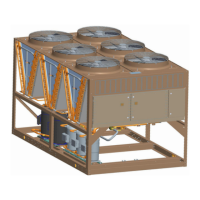
2.04 HEAT EXCHANGERS
A. Air Cooled Condenser:
1. Coils: Internally enhanced, seamless copper
tubes, mechanically expanded into aluminum
alloy ns with full height collars. Subcooling coil
an integral part of condenser. Design working
pressure shall be 650 psig (45 barg).
2. Fans: Shall be dynamically and statically bal-
anced, direct drive, corrosion resistant glass ber
reinforced composite blades molded into low
noise, full airfoil cross section, providing vertical
air discharge from extended orices for efciency
and low sound. Each fan in its own compartment
to prevent cross ow during fan cycling. Guards
of heavy gauge PVC (polyvinyl chloride) coated
steel.
3. Fan Motors: High efciency, direct drive, 6 pole, 3
phase, insulation class “F”, current-protected, To-
tally Enclosed Air-Over (TEAO), rigid mounted,
with double sealed, permanently lubricated, ball
bearings.
2.05 CONTROLS
A. General: Automatic start, stop, operating, and pro-
tection sequences across the range of scheduled
conditions and transients.
B. Microprocessor Enclosure: Raintight NEMA 3R pow-
der painted steel cabinet with hinged, latched, and
gasketed door.
C. Microprocessor Control Center:
1. Condensing Unit control is set for Discharge Air
Temperature Control
2. Automatic control of compressor start/stop, anti-
coincidence and anti-recycle timers, automatic
pump-down shut-down, condenser fans, unit
alarm contacts, and condensing unit operation
from 0°F to 125°F (-18°C to 52°C) ambient.
Automatic reset to normal chiller operation after
power failure.
3. Software stored in non-volatile memory, with
programmed set-points retained in lithium
battery-backed real time clock (RTC) memory
for minimum 5 years.
4. Forty character liquid crystal display, descrip-
tions in English (or Spanish, French, Italian, or
German), numeric data in English (or Metric)
units. Sealed keypad with sections for Setpoints,
Display/Print, Entry, Unit Options & clock, and
On/Off Switch.
5. Programmable Set-points (within Manufacturer
limits): display language; suction pressure set-
ting and control range, remote reset temperature
range, set daily schedule/holiday for start/stop,
manual override for servicing, low and high
ambient cutouts, number of compressors, low
suction pressure cutout, high discharge pressure
cutout, anti-recycle timer (compressor start cycle
time), and anticoincident timer (delay compres-
sor starts).
6. Display Data: Suction temperatures (optional),
low ambient temperature cutout setting, outdoor
air temperature, English or metric data, suction
pressure cutout setting, each system suction
pressure, discharge pressure (optional), dis-
charge air reset via Building Automation System
(by others) via a 4-20milliamp or 0-10 VDC input
with optional BAS interface, anti-recycle timer
status for each system, anti-coincident system
start timer condition, compressor run status, no
cooling load condition, day, date and time, daily
start/stop times, holiday status, automatic or
manual system lead/lag control (when control-
ling based on Discharge Air Temperature only),
automatic lead/lag of compressors within a sys-
tem, compressor starts/operating hours (each),
status of hot gas valves, and fan operation, run
permissive status, number of compressors run-
ning, liquid solenoid valve status, load & unload
timer status.
7. System Safeties: Shall cause individual com-
pressor systems to perform auto shut down;
manual reset required after the third trip in 90
minutes. Includes: high discharge pressure, low
suction pressure, high pressure switch, and mo-
tor protector. Compressor motor protector shall
protect against damage due to high input current
or thermal overload of windings.
8. Unit Safeties: Shall be automatic reset and cause
compressors to shut down if low ambient, or
under voltage.
9. Alarm Contacts: Low ambient, low voltage, low
battery, and (per compressor circuit): high dis-
charge pressure, and low suction pressure.
10. High Ambient Control: Permits unit operation
above 115°F (46°C) ambient.
D. Manufacturer shall provide any controls not listed
above, necessary for automatic condensing unit
operation. Mechanical Contractor shall provide eld
control wiring necessary to interface sensors to the
condensing unit control system.
Guide Specications - continued