FORM 150.63-EG4 (1012)
5JOHNSON CONTROLS
Microcomputer Control Center
All controls are contained in a NEMA 3R cabinet with
hinged and gasketed outer door and includes:
Liquid Crystal Display with Light Emitting Diode backlight-
ing for outdoor viewing:
• Two display lines
• Twenty characters per line
Color coded 12-button non-tactile keypad with sections
for:
DISPLAY/PRINT of typical information:
• Suction temperatures (optional)
• Ambient temperature
• System pressures (each circuit)
• Operating hours and starts (each compressor)
• Print calls up to the liquid crystal display:
• Operating data for the systems
• History of fault shutdown data for up to the last
six fault shutdown conditions
• An RS-232 port, in conjunction with this press-to-print
button, is provided to permit the capability of hard
copy print-outs via a separate printer (by others).
ENTRY section to:
• ENTER setpoints or modify system values SET-
POINTS updating can be performed to:
• Suction pressure setting
• Suction pressure control zone
• Remote reset temperature range
• Set daily schedule/holiday for start/stop
• Manual override for servicing
• Low and high ambient cutouts
• Number of compressors
• Low suction pressure cutout
• High discharge pressure cutout
• Anti-recycle timer (compressor start cycle time)
• Anti-coincident timer (delay compressor starts)
UNIT section to:
• Set clock
• Set options
• Set unit option
Set unit control for Discharge Air Temperature Control or
for Suction Pressure Control (requires Suction Pres sure
Transducers – standard.
UNIT ON/OFF switch
The microprocessor control center is capable of display-
ing the following:
• Suction temperatures (optional)
• Low ambient temperature cutout setting
• Outdoor air temperature
• English or Metric data
• Suction pressure cutout setting
• Each system suction pressure
• System discharge pressure
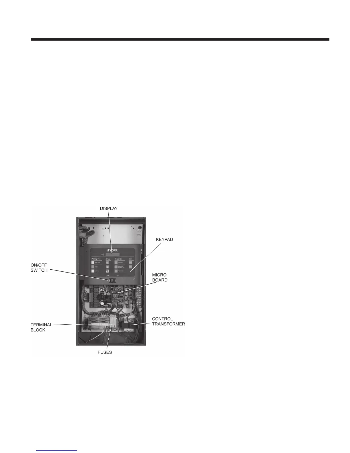
FIG.1 – CONTROL PANEL COMPONENTS