6 JOHNSON CONTROLS
FORM 150.63-EG4 (1012)
Microcomputer Control Center - continued
• Discharge Air Temperature Reset via a YORK
ISN DDC or Building Automation System (by oth
ers) via:
- a pulse width modulated (PWM) input as standard
- a 4-20 milliamp or 0 -10 VDC input, or contact closure
with the optional B.A.S. interface option
• Anti-recycle timer status for each system
• Anti-coincident system start timer condition
• Compressor run status
• No cooling load condition
• Day, date and time
• Daily start/stop times
• Holiday status
• Automatic or manual system lead/lag control
(Discharge Air Temperature control only)
• Automatic lead/lag of compressors within a system
• Compressor starts & operating hours (each compres-
sor)
• Status of hot gas valves, and fan operation
• Run permissive status
• Number of compressors running
• Liquid solenoid valve status
• Load & unload timer status
Provisions are included for: pumpdown at shutdown;
optional remote discharge air temperature reset and two
steps of demand load limiting from an external building
automation system. Unit alarm contacts are standard.
The operating program is stored in non-volatile memory
(EPROM) to eliminate chiller failure due to AC powered
failure/battery discharge. Programmed setpoints are re-
tained in lithium battery-backed RTC memory for 5 years
minimum.
Ambient Kit (High) – Required if units are to operate when
the ambient temperature is above 115°F (46°C). Includes
sun shield panels and discharge pressure transducers.
(This option includes the Discharge Pressure Transducer
/Readout Capabil ity option). (Field mounted).
COMMUNICATIONS
• Native communication capability for N2, BACnet (MS/
TP) and Modbus
• Optional communciation available for LON via eLink
option
POWER PANEL
Each panel contains:
• Compressor power terminals
• Compressor motor starting contactors per
l.E.C.*
• Control power terminals to accept incoming for 115-
1-60 control power
• Fan contactors & overload current protection
The power wiring is routed through liquid-tight conduit to
the compressors and fans.
* International Electrotechnical Commission
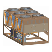
FIG. 2 – POWER PANEL