50 JOHNSON CONTROLS
FORM 150.63-EG4 (1012)
coils from incidental damage,visually screen
internal components, and prevent unauthorized
access to internal components.
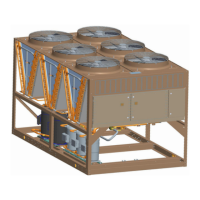
4. Louvered/Wire Panels: Louvered steel panels
on external condenser coil faces, painted as per
remainder of unit cabinet. Heavy gauge, welded
wire-mesh, coated to resist corrosion, around
base of machine to restrict unauthorized access.
J. Service Isolation valves: Service suction and dis-
charge (ball type) isolation valves are added to unit
per system. This option also includes a system high
pressure relief valve in compliance with ASHRAE15.
(Factory-mounted.)
K. Hot Gas By-Pass: Permits continuous, stable opera-
tion at capacities below the minimum step of unload-
ing to as low as 5% capacity (depending on both the
unit & operating conditions) by introducing an articial
load. Hot gas by-pass is installed on only refrigerant
system #1 on two circuited units. (Factory-mounted.)
L. Microprocessor Membrane Keypad Graphics on in
lieu of Standard English:
1. French language.
2. German language.
3. Spanish language.
4. Italian language.
M. Chicago Code Relief Valves to meet Chicago Code
requirements.
N. Building Automation System (EMS) Reset Interface:
Condensing Unit to accept 4 to 20mA, 0 to 10 VDC,
input to reset the discharge air temperature.
O. Sound Reduction (Factory Mounted):
1. Low speed, reduced noise fans
2. Compressor Acoustic Sound Blankets
P. Vibration Isolation (Field Mounted):
1. Neoprene Pad Isolators.
2. 1 Inch Deection Spring Isolators: Level adjust-
able, spring and cage type isolators for mounting
under the unit base rails.
3. 2 Inch Deection Isolators: Level adjustable, re-
strained mounts in rugged welded steel housing
with vertical and horizontal limit stops. Housings
shall be designed to withstand a minimum 1.0g
accelerated force in all directions to 2 inches.
PART 3 - EXECUTION
3.01 INSTALLATION
A. General: Rig and Install in full accordance with
Manufacturers requirements, Project drawings, and
Contract documents.
B. Location: Locate condensing unit as indicated on
drawings, including cleaning and service mainte-
nance clearance per Manufacturer instructions. Ad-
just and level condensing unit on support structure.
C. Components: Installing Contractor shall provide and
install all auxiliary devices and accessories for fully
operational condensing unit.
D. Electrical: Coordinate electrical requirements and
connections for all power feeds with Electrical Con-
tractor (Division 16).
E. Controls: Coordinate all control requirements and
connections with Controls Contractor.
F. Finish: Installing Contractor shall paint damaged and
abraded factory nish with touch-up paint matching
factory nish.
Guide Specications - continued