5725848-XIM-A-0319
Johnson Controls Ducted Systems 11
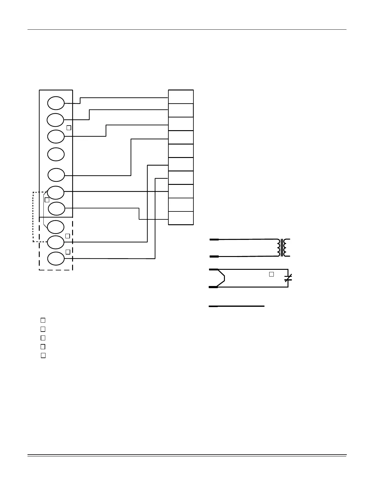
Typical cool/heat control wiring (Smart Equipment™ ZF036-076)
Figure 4: Typical Smart Equipment™ control wiring
Thermostat
The room thermostat should be located on an inside wall
approximately 1422 mm (56”) above the floor where it will not
be subject to drafts, sun exposure or heat from electrical
fixtures or appliances. Follow manufacturer's instructions
enclosed with thermostat for general installation procedure. A
minimum of seven color-coded insulated wires (#18 AWG)
should be used to connect thermostat to unit.
Power and control wiring
Field wiring to the unit must conform to provisions of the
National Electrical Code, ANSI / NFPA No. 70 (in U.S.A.),
current Canadian Electrical Code C22.1 (in Canada) and/or
local ordinances. The unit must be electrically grounded in
accordance with NEC and CEC (as specified above) and/or
local codes. Voltage tolerances, which must be maintained at
the compressor terminals, during starting and running
OCC
C
RC
G
Y2
Y1
W2
W1
X
R
THERMOSTAT
TERMINALS
CONTROL
TERMINAL
BLOCK
TERMINALS ON A
LIMITED NUMBER
OF THERMOSTATS
1
4
3
1
2
4
Second stageŚĞĂƟŶŐŶot required on single stage heĂƟŶg units.
Jumper is required if there is no Smoke Detector circuit.
Jumper is required for any coŵďŝŶĂƟŽŶ of R, RC, or RH.
5
5
OCC is an output from the thermostat to indicate the Occupied ĐŽŶĚŝƟon.
X is an input to the thermostat to display Error Status condiƟons.
3
W2
Y1
G
OCC
Y2
X
R
SD-24
C
W1
2
24V
C
24 VAC
Class 2
SD-24
Jumper Located on Harness
Smoke
Detector
SD-R
24V Output
R
(If No Smoke Detector)
(If Smoke Detector Is Used)
R~Occ Jumper:
Smart Equipment Control boards come from the
factory with a jumper wire between R and OCC
terminals on the thermostat terminal strip. Failure
to remove this jumper will place the unit into the
Occupied mode no matter what the occupancy
demand is from the thermostat or EMS system.
To allow Thermostat or EMS control of the
Occupied mode for the unit, this jumper must be
removed during commissioning.

 Loading...