Maintaining the Cutting Blade
5 - 5
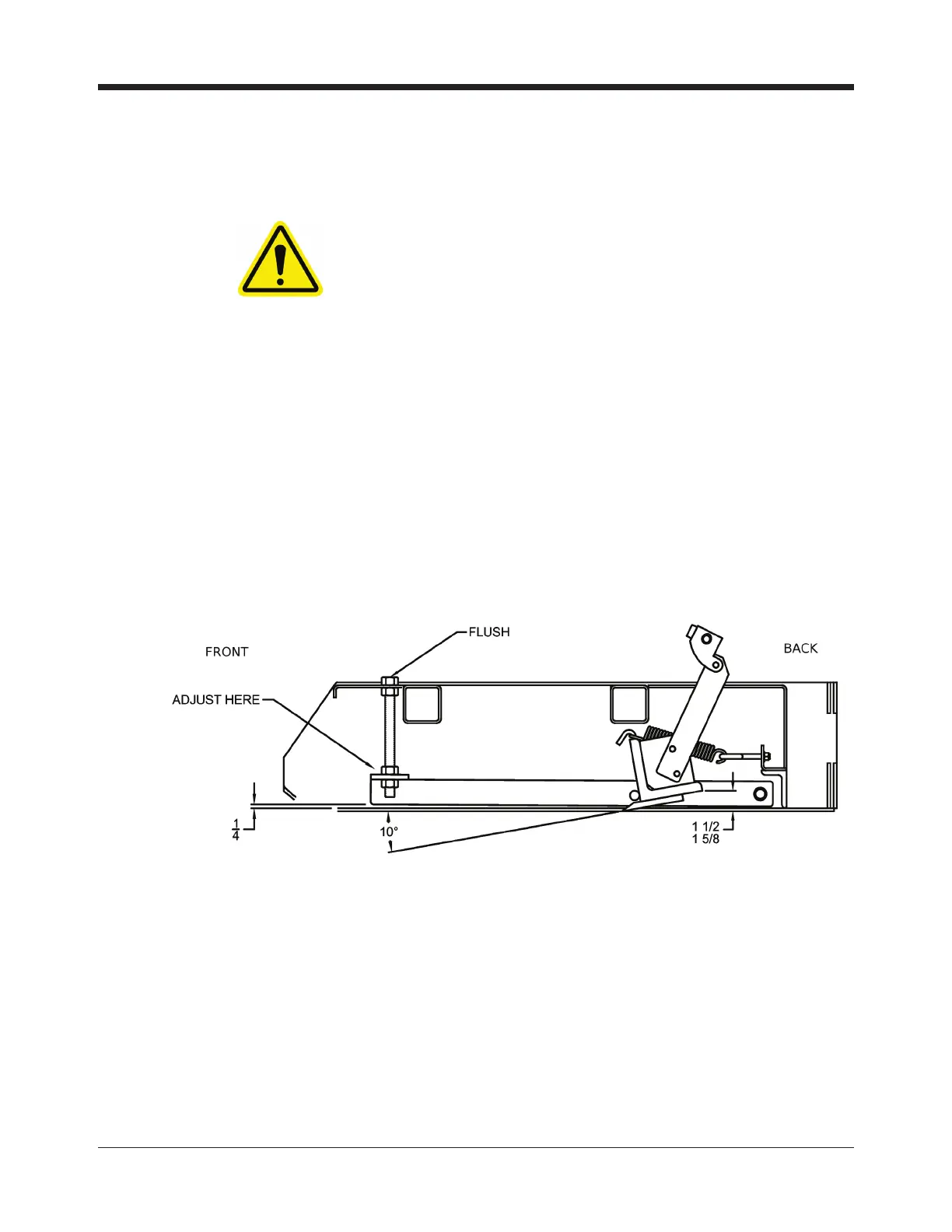
Procedure for Setting Blade Angle and Depth of Cut
WARNING!
Use caution as blade is sharp.
The primary method of setting the blade angle and depth of cut is to set up the blade
holding bar to the dimensions shown below (See gure 5.5). The 1/4" dimension is to be
measured from the top side of the resurfacer runner and the underside of the adjusting bar
closest to the front of the machine. Set the blade holding bar dimension between 1 1/2"
and 1 5/8" (measured from the ground or ice surface to the back edge of the blade holding
bar). On a new 5" blade mounted in the rst set of holes or a 4" blade mounted using the
back set of holes, these dimensions will give you a 10
0
blade angle. A blade width other
than above will represent different dimensions.
Note: If the blade is even with both runners, the majority of the blade will be about 1/16"
below the runner as shown in Figure 5.4. Since a 1/16" cut would normally be quite a
heavy cut, turn the hand wheel counter-clockwise to raise the blade slightly. (With a new
5" wide blade, 1-1/4 turns of the handwheel is equal to approximately 1/16").
Alternate Method for Setting Blade Angle and Height
Step 1: Set the blade at an angle of 10
0
by rotating center hand wheel and using the blade
adjusting tool (Part No. 84-01100). (Figure 5.6)
Step 2: Align leading edge of blade EVEN with BOTH frame runners. It is quite helpful to
use a at washer, a large coin or the blade adjusting tool to check this alignment as shown
on the following page. (Figure 5.7)
Figure 5.5 Aligning the Blade with Frame Runners
 Loading...