13
Media Rewind Upgrade
Installing the Media Rewind Option Kit
10/23/2006 33181L-001 Rev. A
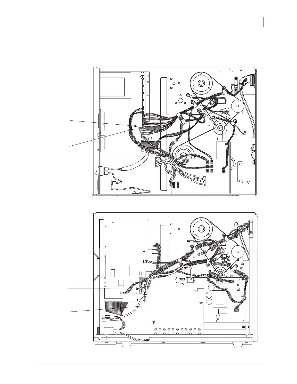
31. See Figure 7. Route the sensor wires through the cable clamps and bring them to the main
logic PCB. Make sure that the wires do not come in contact with any moving parts.
Figure 7 • Sensor Connections
Lower
Take Label
Sensor (J15)
Printer Configurations 10500-0XXX-XXXX and 10500-1XXX-XXXX
Printer Configurations 10500-2XXX-XXXX and 10500-3XXX-XXXX
Lower
Sensor (P1)
Take Label
Upper
Sensor
Take Label
(J16)
Upper
Sensor (P2)
Take Label
S2
J7
J6 J5
J1
J1
J3
J4
J2
J8
J9
J10
J10
J11
J11
J12
J13
J14
J15
J16
J17
J18
J19
J20
J21
DC POWER PCB
AC POWER
PCB
MAIN LOGIC PCB
MAIN LOGIC
PCB
PCMCIA
OPTION
BOARD
AC/DC
POWER
PCB
P6
P25
P27
P8
P2
P1
P3
P32
P31
P19
P5
P10
 Loading...


