Head-Up Sensor Replacement 980358-308A
Preparations
Protect against static discharge. Your work area must be static-safe and include
a properly grounded conductive cushioned mat to hold the printer and a
conductive wrist strap for yourself.
Perform the removal steps of the Bottom Case Replacement procedure (980358-305).
Removal
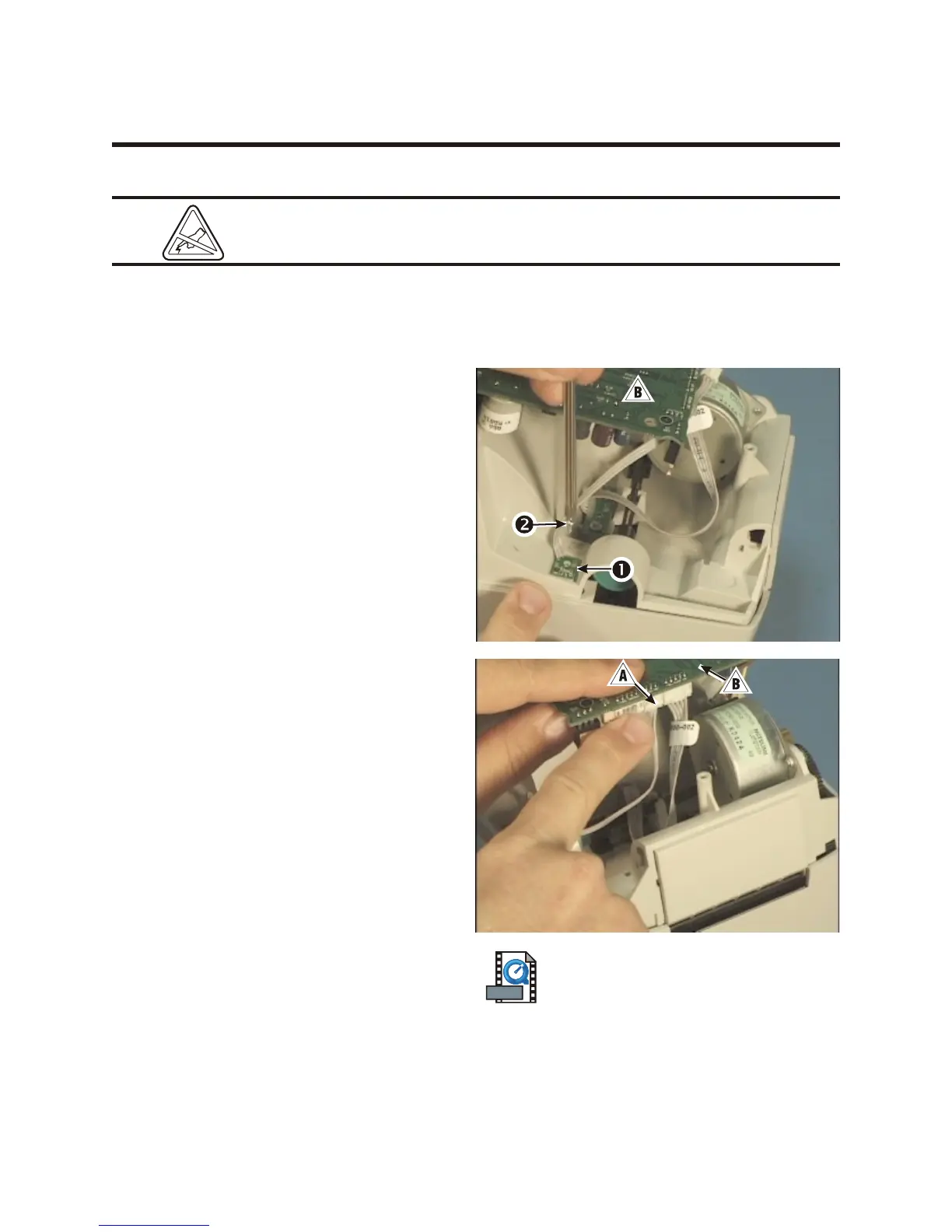
1. Unplug the ribbon cable ! from the sensor
1 where it attaches to the main PCBA ".
Note its location.
2. Use a #1 Phillips to remove the screw 2
that holds the sensor to the bottom of the
media frame.
Assembly
1. Align the sensor so that its ribbon cable is to
the left; then, place it one the bottom of the
media frame.
2. Replace the screw that holds the sensor to
the frame; then, use a #1 Phillips driver to
tighten it.
3. Plug the ribbon cable from the sensor into
its connector on the main PCBA.
Assembling the Printer
Perform the assembly steps of the Bottom Case
Replacement procedure (980358-305). Check
the installation. Turn on the printer and run the
AutoSense routine to get a dump mode
printout. This action tests the printer's media
drive and printing capabilities.
980358-001 Rev. B 57