Feed Button/LED and Top Gap Sensor Replacement - TLP 980358-516A
Preparation
The feed button LED PCB and the top gap (receive) sensor are one assembly. To access them,
perform the removal steps of the Bottom Case (980358-405), Main PCBA (980358-409), Hinge
(980358-413), Upper Case (980358-414), and Ribbon Carriage (980358-415) procedures.
Removal
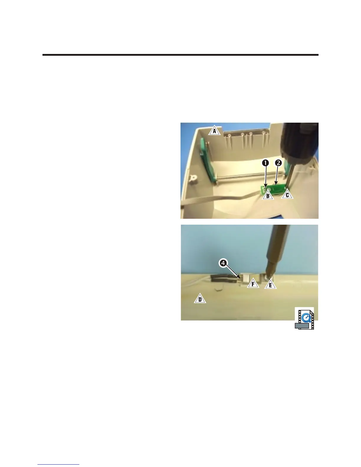
1. In the top cover !, use a #1 Phillips driver
to remove the two screws "# that hold
the PCB 1, and button 2.
2. On the upper frame $, use a #0 Phillips
driver to remove the screw % that holds
the metal brace & and upper gap sensor 4
in place.
3. Lift the opaque button and clear lens away
from the top cover.
Assembly
1. With the top cover upside-down, insert the
both button into place.
2. Align the feed button/LED PCBA so that the
ribbon cable faces the closest sidewall.
3. Replace the two screws that hold the LED
PCBA and use a #1 Phillips driver to
tighten them.
4. Align the top gap sensor so that the ribbon
cable goes to the right of the upper frame.
5. Align the metal brace that holds the upper gap sensor.
6. Replace the screw that holds the brace and sensor and use a #0 Phillips driver to tighten it.
7. Route the sensor's wires through their guides. Refer to the diagram in the Cable Routing section.
980358-001 Rev. B 77