Seite 14/69
Page 14/47JMA-Optic
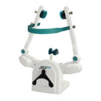
3.3. Elements of the JMA-Optic System
1 IR-Sync LED’s
2 Product label
3 Camera modules left / right
4 Connection socket: external power supply / data transmission
5 Cable guide / strain relief
6 Knurled screw for locking: overhead band
7 Knurled screw for locking: bearing seat
8 Bearing cushions / bearing seat
9 Headband
10 Nose cushion
11 Transport switch
12 IR-Sync LED’s, (lower jaw sensor)
13 Magnetic coupling (lower jaw sensor)
14 Product label, (lower jaw sensor)
15 Power supply, USB socket, (inductive charger)
16 Product label, (inductive charger)
17 Product label, (IR foot switch)
A Status-LED, face bow, “WiFi Connection” (blue)
B Status-LED, face bow, “Measurement active” (green)
C Status-LED, face bow, Power supply / battery charging (orange)
D Status-LED, lower jaw sensor, “Measurement active” (green)
E Status-LED, inductive charger, “Power supply” (green)
F Status-LED, IR foot switch, “Device active” (green), “Battery low” (orange)