4 Information About the Sensor
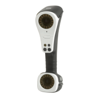
Each configured GOM Scan 1 sensor comprises a defined 3D area in scan
direction within which a measuring object can be scanned.
Such a 3D area is referred to in the following as a “measuring volume”
(MV).
The measuring volume defines the distance of the sensor to the measur‐
ing object.
Info
Depending on the measuring task, dierent measuring volumes are
required.
Each GOM Scan 1 sensor only has one integrated measuring volume
which cannot be changed.
Each individual measuring volume requires a separate GOM Scan 1 sensor.
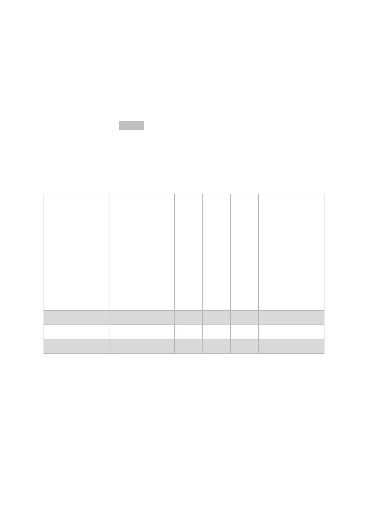
4.1 Sensor Configurations
Sensor model
Measuring volume (MV)
(L x W x H) [mm]
Measuring point distance [mm]
Recommended reference points [Ø mm]
Measuring distance [mm]
Standard calibration objects
GOM Scan 1 (400) 400 x 250 x 300 0.129 3 500 CPA50/480
GOM Scan 1 (200) 200 x 125 x 150 0.060 1.5 450 CPA30/210
GOM Scan 1 (100) 100 x 65 x 70 0.037 0.8 400 CPA10/150
Tab. 3: Sensor configurations
0000002121_003_EN_01-09-2021
Page 10 (24)
 Loading...